
User's Manual

Installation MC-Series High-Power System
998--01 Rev X1
48 CONFIDENTIAL AND PROPRIETARY RadioFrame Networks, Inc.
TRADE SECRET INFORMATION
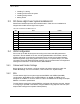
• RF (Tx / Rx / Rx diversity)
• Power
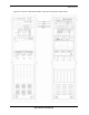
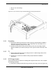
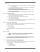
Figure 29 Top of the Rack (TOR), Dual-Band Bulkhead, Cabling and Equipment
4.5.1 Grounding
1 Ground the cabinet ground bar to the site according to Sprint Nextel’s installation
instructions using 2-hole terminal lug. Type is Panduit 2-hole, P/N LCD6-14A, or
equivalent. Required crimp tool is CT-1700.
2 Connect the site ground to the ground at the top of the rack according to Sprint
Nextel’s installation procedures (see Figure 29 for ground location at the top of the
rack).
4.5.2 T1
1 Follow Sprint Nextel procedure for routing the site T1 cable through the top of the
cabinet as shown in Figure 29.
2 Connect the T1 cable to the CSU according to Sprint Nextel’s installation
instructions.
4.5.3 GPS Surge Arrestor
Follow Sprint Nextel’s procedure for installing GPS equipment at the site. Then complete
the following procedure:
3 Install the two RFN-provided GPS surge arrestors at the top of the rack (Figure 29).