
User's Manual

MC-Series High-Power System Installation
998--01 Rev X1
RadioFrame Networks, Inc. CONFIDENTIAL AND PROPRIETARY 47
For complete cabling information, refer to Appendix C “High-Power iDEN Microcell Rack
Stack-Up, 3-Sector (Default) Configuration”.
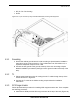
4.3.3 CSU
1 Remove the cabinet mounting rails from the CSU mounting location.
2 While supporting the CSU, slide the CSU into the cabinet mounting position.
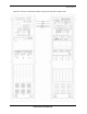
3 Mount the CSU in the location shown in the cabinet illustration earlier in this
section. As necessary, follow the equipment manufacturer's installation procedure
for mounting the CSU in a 19” standard EIA-compliant rack.
4 Connect the RFN-provided ground cable (P/N 820-0609-10; CSU to GND BAR)
between the cabinet ground bar and the grounding lug on the rear of the CSU, and
ensure the connection is tight.
5 Connect the RFN-provided power cable (P/N 820-0615-50; CSU to PDU-CSU) to
the CSU power.
6 Connect the other end of the power cable to the circuit breaker on the PDU.
7 Connect the CSU to each iSC-3 according to Sprint Nextel’s installation procedure.
8 Using a cat-5 cable, connect 10/100 Ethernet port 1 on the CSU to port 8 on the
BIC ERTM for remote-management access.
For complete cabling information, refer to Appendix C “High-Power iDEN Microcell Rack
Stack-Up, 3-Sector (Default) Configuration”.
4.4 Mounting Auxiliary Equipment
Follow Sprint Nextel's procedures for mounting the following auxiliary equipment:
• Powerplant
• Backboard
• Surge arrestors
• Alarm blocks
• Environmental sensors
4.5 Cabinet-to-Site Cabling
Follow Sprint Nextel's procedures for installing the following wiring at the site, and then
complete the procedures in this section to complete the cabinet-to-site cabling. See
Appendix C for top of the rack connections.
• Grounding
• T1
• GPS surge arrestors
• EAS alarm cabling
Warning!
Always connect the power cable to the CSU before connecting the power cable
to the PDU.