
User's Manual

System Definition MC-Series High-Power System
998--01 Rev X1
24 CONFIDENTIAL AND PROPRIETARY RadioFrame Networks, Inc.
TRADE SECRET INFORMATION
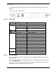
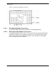
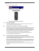
Figure 16 RBS Rear View
2.2.3.1 RBS Ports
Table 4 RBS Ports
Ports Description
Front Ports
SERVICE ACCESS (A, B, C) Sprint Nextel technician local serial access
Rear Ports
Tx / Rx (A, B, C) Input and output for RF Shelf (wiring depends on system configuration)
Fan (A, B, C) Power connector
ALARM INPUT (A, B, C) ALARM serial port on the back of RF Shelf 1, RF Shelf 2, and RF Shelf 3
(respectively); THESE PORTS ARE NOT USED WITH MCMP SYSTEM
10/100 RFN (A, B, C) 100Base-T Ethernet from AIC ERTM Ethernet ports 1, 2 and 3
(respectively)
REF CLOCK not currently used
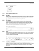
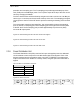
2.2.3.2 RBS Indicators
The front of the RBS has the following LED indicators:
•
STATUS indicator for each group—A, B and C
•
RADIOBLADE TRANSCEIVER STATUS indicators, one for each RadioBlade
transceiver slot in the RBS. LEDs are arranged by group (8 per group A, B and C)
and are numbered consecutively from left to right 1 through 24 (A: 1 through 7; B: 8
through16; and C: 17 through 24).
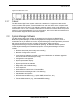
Each RJ-45 port (rear only) has an Ethernet
link LED that indicates connectivity and an
Ethernet
activity LED that indicates Ethernet traffic.
Table 5 RBS Indicator LEDs
LED Indication
STATUS
Indicates timing synchronization for group
RADIOBLADE TRANSCEIVER STATUS
Indicates status of RadioBlade: green = operational;
red = alarm condition; not lit = RadioBlade not present
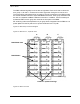
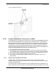
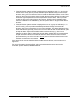
2.2.4 iDEN RadioBlade Transceivers
Each iDEN multi-channel RadioBlade (MCRB) transceiver corresponds to up to six iDEN
carriers in the 800 or 900 MHz band. The MCRB looks similar to Figure 17, with an edge
connector to interface with the slot connector in the RBS. This edge connector provides
all data interfaces and clock inputs to the RadioBlade transceiver. The RF interface
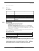
employs two SMA connectors, one for transmit and the other for receive. The MCRB is
distinguished from the older by the notations on the label shown in Figure 18.