
User's Manual

MC-Series High-Power System Final Checkout and Commissioning
998--01 Rev X1
RadioFrame Networks, Inc. CONFIDENTIAL AND PROPRIETARY 49
Note: Make sure the element on the side of the surge arrestor is accessible, depending on
the site configuration.
4 Connect the cable from GPS surge arrestor to the primary iSC-3, rear port GPS
(P/N820-0620-00; GPS-ISC to GPS_1 TOR).
5 Connect the cable from the second GPS surge arrestor to the secondary iSC-3,
rear port GPS (P/N820-0620-00; GPS-ISC to GPS_2 TOR).
6 Connect each GPS surge arrestor to the GPS antenna coax according to Sprint
Nextel’s installation procedures.
4.5.4 EAS Alarm Cabling
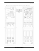
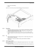
1 Follow Sprint Nextel’s procedure for routing the two 50-pair alarm cables through
the top of the cabinet, as shown in Figure 29.
2 Connect the two 50-pair alarm cables to the back of the EAS:
EAS: USER ALARM / CONTROL
EAS: SYSTEM ALARM / CONTROL
3 Terminate the two 50-pair alarm cables to the two blocks on the backboard, making
sure that each cable is connected to its specific block.
4.5.5 RF (Tx / Rx / Rx diversity)
The MC-Series High-Power system cabinet provides the following RF loads at the top of
the rack for connection to the site RF distribution system:
• Tx 1, Tx 2, Tx 3
• Rx 1, Rx 2, Rx 3
• DIV 1, DIV 2, DIV 3
Connect the female N-type connectors to the onsite RF distribution system (antenna,
DAS, etc.).
4.5.6 Power
Connect the powerplant to the PDU using two two-hole terminal lugs. Type is Panduit 2-
hole, P/N LCD6-14A, or equivalent. Crimp tool needed: CT-1700.
5 Final Checkout and Commissioning
The procedures in this chapter describe final checkout for each portion of the MC-Series
High-Power system. This chapter describes procedures for:
• Prerequisites
• Checkout procedures
• Final checkout setup
Warning!
Verify that all breakers in the PDU are in the OFF position prior to proceeding.
Leave them in the OFF position until instructed otherwise.