
User's Manual

MC-Series High-Power System System Definition
998--01 Rev X1
RadioFrame Networks, Inc. CONFIDENTIAL AND PROPRIETARY 21
provides conversion of the 10Base2 connection at the iSC to a 10BaseT connection in
the BIC.
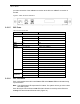
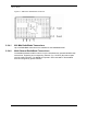
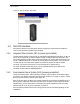
Figure 9 CRTC Ports and Indicators
2.2.1.5 BIC Ports
Table 3 Ports in the BIC
Card Port Description
Front
Ports 1-7 (RJ-45) not currently used
Port 8 (RJ-45) Sprint Nextel technician local Ethernet access
BIC CRIC
EIA-232 9-pin serial port Sprint Nextel technician local serial access
BPC
N/A N/A
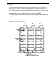
Back
Port 1 (RJ-45) CRTC 1 Port 10BaseT
Port 2 (RJ-45) AIC ERTM port 4
Port 3 (RJ-45) CRTC 2 Port 10BaseT (Optional)
Port 4 (RJ-45) not currently used
Port 5 (RJ-45) RF Shelf 1 10/100 Port 1
Port 6 (RJ-45) RF Shelf 2 10/100 Port 1
Port 7 (RJ-45) RF Shelf 3 10/100 Port 1
Port 8 (RJ-45) Remote Ethernet connectivity (DNX-1u Ethernet)
5 MHz/1PPS IN iSC-3 5-MHz/1PPS port
5 MHz/1PPS OUT not currently used (no terminator required)
ERTM
GPS ANT not currently used
10Base2 – iSC ISC-3 10Base2 port
CRTC 1
10BaseT – iSC BIC ERTM port 1
10Base2 – iSC ISC-3 10Base2 port
CRTC 2
(Optional)
10BaseT – iSC BIC ERTM port 1
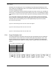
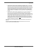
2.2.1.6 BIC Indicators
Each card installed in the BIC has a Power LED and a Status LED that indicates timing
synchronization.
Note: The CRIC Status LED represents PLL status. The system will not go active unless
this LED is green.
Each RJ-45 port has an Ethernet link LED that indicates connectivity and an Ethernet
activity LED that indicates Ethernet traffic (Figure 10).