
User's Manual
MC-Series System Installation & Testing
Scheduled and Unscheduled Maintenance
RadioFrame Networks, Inc.
93
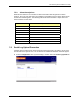
9 In System Manager, refresh the RBS Status page until the RadioBlade icon status bar
changes from red (not present) to yellow (present and locked). This will take approximately
three minutes.
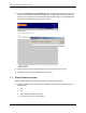
10 Unlock the RadioBlade.
On the RadioBlade Statistics page, the State of the RadioBlade will change from 2 (locked)
to 11 (unlocked).
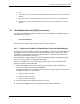
7.8.2 Replacing a Chassis: BIC, AIC, or RBS
1 Power down RFN equipment in the following order using circuit breakers on the PDU:
• BIC
• AIC
• RBS 1 (power down RBS 2 and RBS 3 if they are present)
• RF shelf 1, 2, and 3
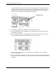
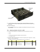
2 Disconnect cabling from the back of the chassis to be replaced (refer to Appendix C: Cabling
Diagrams: 3-Sector Configuration).
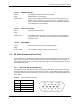
For the BIC, disconnect the following cabling from the rear of the BIC only:
Index Part Number Disconnect From To Type
P_11 820-0614-00 BIC: power PDU: BIC power
G_13 820-0609-00 BIC: ground GND BAR ground
DAT_4* 111-0565-00 BIC: ERTM PORT 1 BIC: CRTC 10baseT - ISC UTP
DAT_5 111-0565-00 BIC: ERTM PORT 2 AIC: ERTM PORT 4 UTP
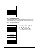
locking arm
locking arm