
User's Manual
MC-Series System Installation & Testing
System Description
28 RadioFrame Networks, Inc.
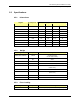
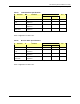
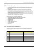
2.5.9.1 Frequency of Operation
Band Receive Frequency (MHz) Transmit Frequency (MHz)
800E 806.0125 to 824.9875 851.0125 to 869.9875
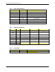
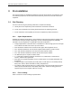
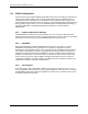
2.5.9.2 Transmitter Performance Summary
Value Parameter
1
Condition
Min Typ Max
Unit
2
Tx Output Power per
carrier (maximum)
Typical output power +8.0 +10 +12 dBm
Tx Power Output
Range per carrier
-20 +10 dBm
Tx Output Power
Variation
-20dBm ≤ Pout ≤ +10 dBm
851.0125 ≤ f ≤ 869.9875 MHz
-2.0 2.0 dB
Transmit port VSWR Referenced to a 50 ohm
impedance
2:1 -
Downlink Signal Quality
Estimator (SQE)
Average value 30 dB
Occupied bandwidth Per carrier 18.5 kHz
RF Frequency
Tolerance (TX)
Average frequency ± 50 Hz
Note 1: Unless otherwise stated, all values are referenced to the top of the rack.
Note 2: At maximum rated RF output power, all spurious and harmonic emissions should be at the noise floor. No
combination of IM products or any other spurious emissions generated in the transmitting equipment should exceed the
underlying noise floor in the operating band. Also, the Tx output power level is a function of the datafill parameters as well
as the RF shelf attenuator setting.
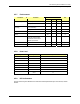
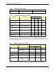
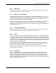
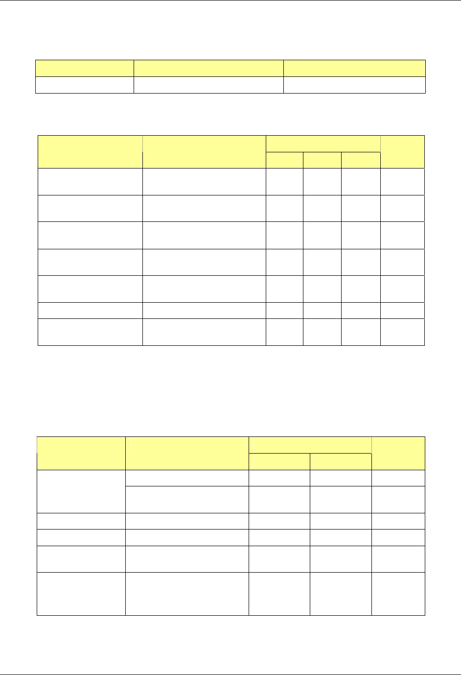
2.5.9.3 Receiver Performance Summary
Value Parameter
1
Condition
Min Max
Unit
2% BER -106 -36 dBm
Rx Input Level
Absolute Maximum where
no damage occurs
+10 dBm
Residual BER Input signal of –80 dBm 0.1 %
Input IP3 Single channel input +10 dBm
Adjacent Channel
Selectivity*
Quad-channel input -32 dBc
2
IMD Immunity P
rx
= -103 dBm, BER<2%
∆ f
1
= ± 1 MHz
∆ f
2
= ± 2 MHz
-50 dBm
Note 1: Unless otherwise stated, all values are referenced to the top of the rack.
Note 2: Two-tone test ∆ f
1
is a CW interferer, ∆ f
2
is an iDEN modulated interferer; refer to RFN test document.