
User's Manual
MC-Series System Installation & Testing
Scheduled and Unscheduled Maintenance
96 RadioFrame Networks, Inc.
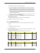
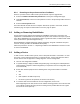
Index Part Number Disconnect From To Type
RF_15 820-0610-30 RF Shelf 2: TX OUT TOR: Tx 2
RF cable
RF_16 820-0610-30 RF Shelf 2: RX IN TOR: Rx 2
RF cable
AL_2 820-0607-00 RF Shelf 2: ALARM RBS: ALARM INPUT B serial
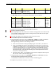
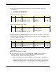
For RF Shelf 3, disconnect the following cabling from the rear of RF Shelf 3:
Index Part Number Disconnect From To Type
P_3 820-0616-10 RF Shelf 3: power PDU: RF 3 power
G_5 820-0609-00 RF Shelf 3: ground GND BAR ground
RF_1 820-0611-20 RF Shelf 3: Tx IN C RBS 1: Tx C
RF cable
RF_4 820-0611-20 RF Shelf 3: Rx OUT C RBS 1: Rx C
RF cable
RF_9 820-0610-30 RF Shelf 3: TX OUT TOR: Tx 3
RF cable
RF_10 820-0610-30 RF Shelf 3: RX IN TOR: Rx 3
RF cable
AL_1 820-0607-00 RF Shelf 3: ALARM RBS: ALARM INPUT C serial
3 Remove the RF shelf from the rack, and package it for shipment.
24 Mount the replacement RF shelf.
While supporting the RF shelf, slide it into the cabinet mounting position. Secure the RF shelf
to the cabinet mounting rails using the four mounting screws provided with the unit. Tighten
the screws to 4.5 Nm (40 in-lb).
35 Reconnect the cabling to the replacement chassis as defined in Step 2.
Use the SMA torque wrench for all SMA connectors.
6 Using the breakers on the PDU, turn up the BIC, AIC, and RBS 1 (and RBS 2 and RBS 3 if
present), and then verify that the components are operational before proceeding.
Wait approximately 3 minutes for the following indicators:
• RBS: The STATUS LED for each group will light green in this order: A, B, and then C.
• RBS: The RADIOBLADE STATUS LEDs will light red and then green for each present
RadioBlade. If no RB is present, the LED will not light. To verify the contents of the RBS,
pull out the shelf (powering off is not required) and inspect the RadioBlades and their
respective status LEDs. Reinsert the RBS. To do this, press up on one side rail locking
arm and press down on the other side rail locking arm, and then push the unit into the
rack (see the following illustration).
• BIC CRIC and AIC CRIC: The POWER and STATUS LEDs will light red and then green.
All other BIC and AIC card LEDs will light green.
7 Using the breaker on the PDU, turn up RF Shelf 1, RF Shelf 2, and RF Shelf 3 and verify
that each RF shelf is operational before proceeding.
The POWER and ALARM LEDs on the front of the RF Shelf will light green.
8 Complete the procedures in section 5.4, 5.5 and 5.6.