
User's Manual
MC-Series System Installation & Testing
Scheduled and Unscheduled Maintenance
94 RadioFrame Networks, Inc.
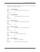
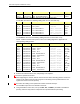
Index Part Number Disconnect From To Type
DAT_6 111-0001-02 BIC: CRTC 10base2 - ISC ISC 1: 10B2-1 COAX
CLK_1 111-0001-02 BIC: ERTM 5MHz/1PPS IN ISC 1: SITE REF OUT 1 COAX
* Remove both ends of this cable and keep it for the replacement BIC.
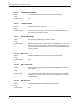
For the AIC, disconnect the following cabling from the rear of the AIC only:
Index Part Number Disconnect From To Type
P_12 820-0614-10 AIC: power PDU: AIC power
G_13 820-0609-00 AIC: ground GND BAR ground
DAT_1 111-0566-00 AIC: ERTM PORT 1 RBS 1: 10/100 RFN A UTP
DAT_2 111-0566-00 AIC: ERTM PORT 2 RBS 1: 10/100 RFN B UTP
DAT_3 111-0566-00 AIC: ERTM PORT 3 RBS 1: 10/100 RFN C UTP
DAT_5 111-0565-00 AIC: ERTM PORT 4 BIC: ERTM PORT 2 UTP
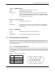
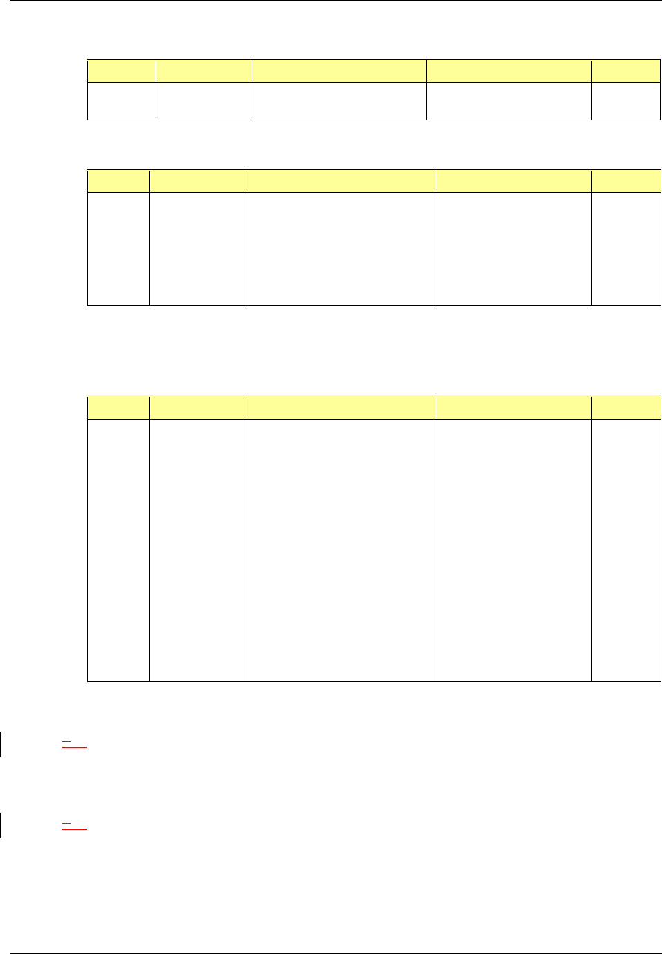
For the RBS 1, disconnect the following cabling from the rear of the RBS 1 only:
NOTE: If RBS 2 and RBS 3 are present, refer to the cabling diagrams in Appendix C for
corresponding cabling indexes.
Index Part Number Disconnect From To Type
P_6 820-0616-50 RBS 1: power PDU: RBS 1 power
G_8 820-0609-00 RBS 1: ground GND BAR ground
RF_1 820-0611-20 RBS 1: Tx A RF Shelf 1: Tx IN A
RF cable
RF_4 820-0611-20 RBS 1: Rx A RF Shelf 1: Rx OUT A
RF cable
AL_1 820-0607-00 RBS: ALARM INPUT A RF Shelf 1: ALARM serial
DAT_1 111-0566-00 RBS 1: 10/100 RFN A AIC: ERTM PORT 1 UTP
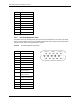
RF_2 820-0611-20 RBS 1: Tx B RF Shelf 2: Tx IN B
RF cable
RF_5 820-0611-20 RBS 1: Rx B RF Shelf 2: Rx OUT B
RF cable
AL_2 820-0607-00 RBS: ALARM INPUT B RF Shelf 2: ALARM serial
DAT_2 111-0566-00 RBS 1: 10/100 RFN B AIC: ERTM PORT 2 UTP
RF_3 820-0611-20 RBS 1: Tx C RF Shelf 3: Tx IN C
RF cable
RF_6 820-0611-20 RBS 1: Rx C RF Shelf 3: Rx OUT C
RF cable
AL_3 820-0607-00 RBS: ALARM INPUT C RF Shelf 3: ALARM serial
DAT_3 111-0566-00 RBS 1: 10/100 RFN C AIC: ERTM PORT 3 UTP
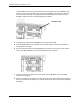
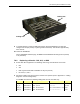
3 Remove the chassis from the rack, and package it for shipment.
24 Mount the replacement chassis.
While supporting the chassis, slide the chassis into the cabinet mounting position. Secure the
chassis to the cabinet mounting rails using the four mounting screws provided with the unit.
Tighten the screws to 4.5 Nm (40 in-lb).
35 Reconnect the cabling to the replacement chassis as defined in Step 2.
Use the SMA torque wrench for all SMA connectors.
6 Using the breakers on the PDU, turn up the BIC, AIC, and RBS 1 (and RBS 2 and RBS 3 if
present), and then verify that the components are operational before proceeding.