
User's Manual

MC-Series System Installation & Testing
Scheduled and Unscheduled Maintenance
104 RadioFrame Networks, Inc.
7.9.3.2 BPC (BIC) or BPC+SPAM (AIC)
1
Before replacing any card (board) in the BIC or AIC, power down RFN equipment in the
following order using circuit breakers on the PDU:
• BIC
• AIC
• RBS 1 (power down RBS 2 and RBS 3 if they are present)
• RF Shelves 1, 2 and 3
2 Always use a static grounding wrist strap before handling any board—do not attach the wrist
strap to any painted surface on the chassis unit.
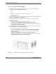
3 Facing the chassis unit, remove the BPC that is to be replaced, or the blank faceplate,
following these guidelines:
• Loosen the blue knurled knobs on both sides of the board.
• Pull firmly on the tabs located on the bottom of the BPC you are replacing.
• Gently slide the BPC straight out and away from the chassis unit so as not to damage
any components contained on the board.
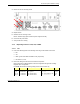
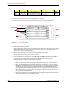
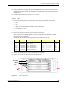
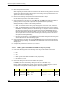
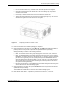
4 Remove the BPC from its antistatic packaging and insert it into the chassis unit as shown in
the following illustration, and follow these guidelines:
• Do not jam the board in any way while inserting it.
• Do not mount the board in any orientation other than that specified in the diagram.
• Insert the board straight into the chassis unit so as not to damage any components
contained on the board.
• Press firmly to seat the board into the connectors within the chassis unit.
• Tighten the blue knurled knobs on each end of the board finger tight only—do not use a
screwdriver to tighten the screws and do not over tighten.
Figure 35 Replacing the BPC in the BIC or the BPC+SPAM in the AIC.