
Installation Guide
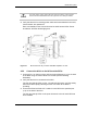
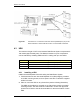
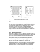
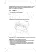
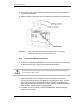
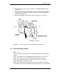
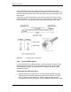
Table Of Contents
- Title
- Contents
- Introduction
- System Description
- Pre-Installation
- Receipt of Equipment
- Site Planning
- Main Rack and Supporting Hardware
- Remote ACUs
- RFUs
- RadioBlades
- RAPs
- URU
- Interconnecting Cabling
- Main Rack Configuration
- RF Planning
- Site Survey
- Alarm Configuration
- Tools Required
- Installation
- Equipment Commissioning
- iDEN Interface
- Power Plant
- RadioFrame System
- Coverage Validation
- Site Acceptance Guidelines
- RadioFrame System Functionality Test
- RadioFrame System iDEN Functionality Test
- Interconnect & Dispatch Setup & Voice Quality
- Packet Data Service Connection and Latency
- Short Message Service
- Handover and Cell Reselection
- Interconnect Connection Stability and SQE Performance
- Dispatch Connection Stability
- Idle SQE Testing and Validation
- System Self-Recovery Test
- Packet Data Stability and Throughput
- Validation of ‘Unable to Key BR’ Alarm
- Rectifier & AC Power Alarms
- iSC-3 Functionality Test
- RadioFrame System iDEN Functionality Test
- Connecting the RFS to the Customer LAN
- Operations and Maintenance
- Appendixes

RadioFrame System
Installation
RFN_3.1 Beta 73
mounting this unit in any fashion not recommended and approved by
RadioFrame Networks. This includes, but is not limited to, damage to, or loss of,
equipment, loss of data, or loss of profit, even if RadioFrame Networks was
advised of the possibility of such damages
4.4.1.1 Wall Mount
1 Place the 11” x 17” drawing template (P/N 981-1020-00) on the wall where
the RadioFrame Unit is to be mounted.
2 Mark the two locations indicated on the template.
3 Screw the two supplied anchors into the locations as shown in the following
diagram.
4 Screw the two supplied screws into the anchors, leaving approximately 1/4”
of each screw exposed.
5 Hang the RFU on the anchors and fully tighten both screws.
Figure 23 A wall mount requires two screws to anchor the RFU.
4.4.1.2 Ceiling Mount
1 Place the 8.5” x 11” drawing template (P/N 981-1010-00) on the ceiling where
the RFU is to be mounted.
2 Mark the four locations indicated on the template.
3 Drill four holes with the appropriately sized bit: 3/16” for the provided wood
screws, or 9/32” for 1/4” bolts (bolts not provided).
If using the provided wood screws, ensure that all four screws penetrate
wood. Otherwise, use alternative mounting screws or bolts to secure the
ceiling bracket.