
Installation Guide
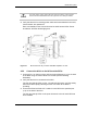
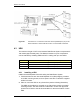
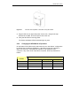
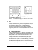
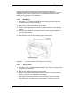
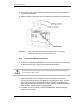
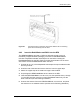
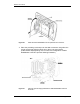
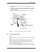
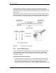
Table Of Contents
- Title
- Contents
- Introduction
- System Description
- Pre-Installation
- Receipt of Equipment
- Site Planning
- Main Rack and Supporting Hardware
- Remote ACUs
- RFUs
- RadioBlades
- RAPs
- URU
- Interconnecting Cabling
- Main Rack Configuration
- RF Planning
- Site Survey
- Alarm Configuration
- Tools Required
- Installation
- Equipment Commissioning
- iDEN Interface
- Power Plant
- RadioFrame System
- Coverage Validation
- Site Acceptance Guidelines
- RadioFrame System Functionality Test
- RadioFrame System iDEN Functionality Test
- Interconnect & Dispatch Setup & Voice Quality
- Packet Data Service Connection and Latency
- Short Message Service
- Handover and Cell Reselection
- Interconnect Connection Stability and SQE Performance
- Dispatch Connection Stability
- Idle SQE Testing and Validation
- System Self-Recovery Test
- Packet Data Stability and Throughput
- Validation of ‘Unable to Key BR’ Alarm
- Rectifier & AC Power Alarms
- iSC-3 Functionality Test
- RadioFrame System iDEN Functionality Test
- Connecting the RFS to the Customer LAN
- Operations and Maintenance
- Appendixes

RadioFrame System
Installation
RFN_3.1 Beta 71
Figure 21 The URU can be placed or mounted on any flat surface.
3 Plug the URU into an approved power source, then, using the tie wrap
attached to the URU, secure the power cord to the unit.
4 Verify that the URU is receiving power.
The Power and Status LEDs should both light as green.
4.3.2 Changing the URU Mode of Operation
On the bottom of the URU is a dip switch that is in the “Auto Sense” configuration
by default (see the following illustration). If the URU receives 48 Volts DC on
either “IN” connector, it will output 48 Volts DC on its respective “OUT”
connector. If any other mode of operation is required, set the dip switches as
follows:
Desired Mode of Operation
DIP Switch
Number
Auto Sense Power In/Out 48VDC Output On 48VDC Output Off
1 OFF ON OFF
2 OFF ON OFF
3 ON OFF OFF
4 ON OFF OFF