
Installation Guide

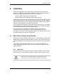
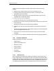
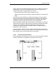
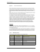
Table Of Contents
- Title
- Contents
- Introduction
- System Description
- Pre-Installation
- Receipt of Equipment
- Site Planning
- Main Rack and Supporting Hardware
- Remote ACUs
- RFUs
- RadioBlades
- RAPs
- URU
- Interconnecting Cabling
- Main Rack Configuration
- RF Planning
- Site Survey
- Alarm Configuration
- Tools Required
- Installation
- Equipment Commissioning
- iDEN Interface
- Power Plant
- RadioFrame System
- Coverage Validation
- Site Acceptance Guidelines
- RadioFrame System Functionality Test
- RadioFrame System iDEN Functionality Test
- Interconnect & Dispatch Setup & Voice Quality
- Packet Data Service Connection and Latency
- Short Message Service
- Handover and Cell Reselection
- Interconnect Connection Stability and SQE Performance
- Dispatch Connection Stability
- Idle SQE Testing and Validation
- System Self-Recovery Test
- Packet Data Stability and Throughput
- Validation of ‘Unable to Key BR’ Alarm
- Rectifier & AC Power Alarms
- iSC-3 Functionality Test
- RadioFrame System iDEN Functionality Test
- Connecting the RFS to the Customer LAN
- Operations and Maintenance
- Appendixes

Method of Procedure
Installation
66 RFN_3.1 Beta
Figure 18 Environmental Alarm Block
Each of the site alarm contacts are normally closed and connected to the EAS
through a 50-pin Champ cable that connects to a punch block. All alarm contact
pairs must be dry (isolated from ground). Most alarm connections are inputs.
Outputs provide a dry relay closure rated at 0.5 Amps, 30 Vrms or 60 Vdc, 10VA
max.
Alarm wiring for the main rack terminates directly to the EAS rear panel. Connect
the alarm cable as shown in the previous illustration.
Four outputs on the User Alarm/Control and System Alarm/Control connectors
are available for customer-defined applications. Diode suppression of inductive
surges is required if anything but a resistive load is connected to this output.
Eighteen customer-defined alarm inputs are available on the User Alarm/Control
connector. The alarms are reported to the Operations and Maintenance Center
(OMC) by the respective alarm code. The OMC must be programmed with the
proper alarm name corresponding to each code. All connections on User
Alarm/Control and System Alarm/Control connectors must be defined and
provided to the OMC to insure the effectiveness of monitoring those alarms.
Backboard
A wall mounted AC grade fire-rated plywood backboard (1/2” x 4’ x 4’) must be
provided within the site. Reserve a two square foot area on the Telco backboard
for dedicated system use.
A 117 VAC dual receptacle outlet (3 prong) should be installed on or adjacent to
the Telco backboard. This outlet can be used for accessories, such as modems
and other AC powered devices. It may also be used as a general service outlet.
4.1.2.3 Mandatory Alarms
RFN recommends site installation of the following alarms:
Alarm Code Alarm Type EAS standard alarm connection
219 Intrusion alarm predefined input, site entry
220 High temperature predefined input, site high ambient temperature
221 Low temperature predefined input, site low ambient temperature
222 Smoke detector (120 VAC) predefined input, site smoke detector
242 Power Plant alarms: AC power failure
243 low DC voltage
244 high DC voltage
245 breaker alarm failure