
Installation Guide
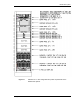
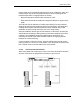
Table Of Contents
- Title
- Contents
- Introduction
- System Description
- Pre-Installation
- Receipt of Equipment
- Site Planning
- Main Rack and Supporting Hardware
- Remote ACUs
- RFUs
- RadioBlades
- RAPs
- URU
- Interconnecting Cabling
- Main Rack Configuration
- RF Planning
- Site Survey
- Alarm Configuration
- Tools Required
- Installation
- Equipment Commissioning
- iDEN Interface
- Power Plant
- RadioFrame System
- Coverage Validation
- Site Acceptance Guidelines
- RadioFrame System Functionality Test
- RadioFrame System iDEN Functionality Test
- Interconnect & Dispatch Setup & Voice Quality
- Packet Data Service Connection and Latency
- Short Message Service
- Handover and Cell Reselection
- Interconnect Connection Stability and SQE Performance
- Dispatch Connection Stability
- Idle SQE Testing and Validation
- System Self-Recovery Test
- Packet Data Stability and Throughput
- Validation of ‘Unable to Key BR’ Alarm
- Rectifier & AC Power Alarms
- iSC-3 Functionality Test
- RadioFrame System iDEN Functionality Test
- Connecting the RFS to the Customer LAN
- Operations and Maintenance
- Appendixes

Method of Procedure
Installation
64 RFN_3.1 Beta
Perform the following steps to properly install the main rack within the site
building:
1 Measure the mounting location for the main rack within the row.
2 Carefully mark the mounting holes with a pencil, as indicated on the
appropriate main rack footprint.
3 Drill the marked mounting holes to the appropriate depth of the mounting
hardware with a hammer drill and bit.
4 Insert an anchor into the drilled hole.
If necessary, tap the anchor into place using a hammer.
5 Remove the four screws securing the bottom kick panel to the front and back
of the main rack.
Remove the kick panel and set aside during installation.
6 Carefully move the main rack into the position indicated by the holes in the
floor.
Adjust and level the main rack as necessary to align the rack mounting holes
with the pre-drilled holes in the floor.
7 Secure the main rack to the site floor with the locally procured mounting
hardware.
8 If required, connect adjacent cabinets to each other using ganging hardware.
4.1.2 Auxiliary Equipment
Auxiliary equipment for the main rack includes:
• GPS antenna
• Environmental alarm block
• Mandatory alarms
• Optional alarms
• Surge arrestors
• Grounding
• Cable supports
4.1.2.1 GPS Antennas
When locating the GPS antennas, install vertical mast (or antenna mount) at a
location that provides a line of sight to as much of the horizon as possible. Solid
buildings and overhanging trees will block the 1.575 GHz signal and cut down on
the amount of sky visible and therefore the number of satellites the antenna can
see. Satisfactory performance can be achieved with as much as 25 percent of