
Installation Guide
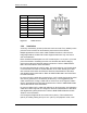
Table Of Contents
- Title
- Contents
- Introduction
- System Description
- Pre-Installation
- Receipt of Equipment
- Site Planning
- Main Rack and Supporting Hardware
- Remote ACUs
- RFUs
- RadioBlades
- RAPs
- URU
- Interconnecting Cabling
- Main Rack Configuration
- RF Planning
- Site Survey
- Alarm Configuration
- Tools Required
- Installation
- Equipment Commissioning
- iDEN Interface
- Power Plant
- RadioFrame System
- Coverage Validation
- Site Acceptance Guidelines
- RadioFrame System Functionality Test
- RadioFrame System iDEN Functionality Test
- Interconnect & Dispatch Setup & Voice Quality
- Packet Data Service Connection and Latency
- Short Message Service
- Handover and Cell Reselection
- Interconnect Connection Stability and SQE Performance
- Dispatch Connection Stability
- Idle SQE Testing and Validation
- System Self-Recovery Test
- Packet Data Stability and Throughput
- Validation of ‘Unable to Key BR’ Alarm
- Rectifier & AC Power Alarms
- iSC-3 Functionality Test
- RadioFrame System iDEN Functionality Test
- Connecting the RFS to the Customer LAN
- Operations and Maintenance
- Appendixes

Method of Procedure
Pre-Installation
56 RFN_3.1 Beta
Cables shall be separated by at least 5.1 cm (2 in.) from AC power conductors.
Refer to NFPA 70, Article 800-52 for more information.
CAT 5 cables installed in ducts, plenums, and other air-handling spaces shall be
installed in accordance with other sections of this document and NFPA 70, Article
300-22. Also refer to NFPA 70, Article 645.
CAT 5 cables installed in hazardous areas as defined in NFPA 70, Article 500
shall be installed in accordance with NFPA 70, Article 500 and any other
applicable electrical and building codes.
CAT 5 cable shall not be attached by any means to the exterior of a conduit or
other raceway as a means of support. Refer to NFPA 70, Article 725-54 and
NFPA 70, Article 800-52 for more information.
Suspended ceiling support rods and wires may be used as a means of support
for computer network cabling if used in conjunction with appropriate cable
fasteners. Refer to ANSI/TIA/EIA-569-A and CSA-T530 for more information.
CAT 5 cables shall not be laid directly on the tiles of a false ceiling. Refer to
ANSI/TIA/EIA-569-A and CSA-T530 for more information.
CAT 5 cables shall not be run from one building to another building. If the
computer network needs to
be extended to another building, a specific cabling
system shall be engineered. Options for extending from one building to another
may include the
use of fiber optic cable or a T1. Computer network cabling
entering and/or leaving a building shall be properly grounded and protected from
surges as required elsewhere in this document.
3.9.4.4 Testing
Every effort should be made to ensure a quality installation of the computer
network cabling system. Even the best installation effort cannot guarantee a
properly working system. It is therefore required that a computer network cabling
system be tested for proper performance.
The procedures and specifications in the TIA/EIA Telecommunications System
Bulletin (TSB) 67 shall be used for this testing. TSB 67 has four primary
parameters to test. Below is an overview of the four test parameters needed to
assure a properly working system.
Wire map
The wire map test is used to verify wire pair to pin termination at each end of the
cable and to check for installation connectivity errors. It is recommended that
100% of cables be tested using a testing tool such as Microtest® Microscanner™
Pro. (Be sure the tester can check for a “split pair” configuration).
Each of the 8 conductors in the cable are tested for:
• Conductor continuity to the remote end of the cable