
Installation Guide
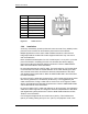
Table Of Contents
- Title
- Contents
- Introduction
- System Description
- Pre-Installation
- Receipt of Equipment
- Site Planning
- Main Rack and Supporting Hardware
- Remote ACUs
- RFUs
- RadioBlades
- RAPs
- URU
- Interconnecting Cabling
- Main Rack Configuration
- RF Planning
- Site Survey
- Alarm Configuration
- Tools Required
- Installation
- Equipment Commissioning
- iDEN Interface
- Power Plant
- RadioFrame System
- Coverage Validation
- Site Acceptance Guidelines
- RadioFrame System Functionality Test
- RadioFrame System iDEN Functionality Test
- Interconnect & Dispatch Setup & Voice Quality
- Packet Data Service Connection and Latency
- Short Message Service
- Handover and Cell Reselection
- Interconnect Connection Stability and SQE Performance
- Dispatch Connection Stability
- Idle SQE Testing and Validation
- System Self-Recovery Test
- Packet Data Stability and Throughput
- Validation of ‘Unable to Key BR’ Alarm
- Rectifier & AC Power Alarms
- iSC-3 Functionality Test
- RadioFrame System iDEN Functionality Test
- Connecting the RFS to the Customer LAN
- Operations and Maintenance
- Appendixes

Method of Procedure
Pre-Installation
50 RFN_3.1 Beta
location to achieve single point grounding). The Smart Jack and T1 suppressor
are located on the Telco board near the T1 line entrance to the site. The CSU is
located in main rack. The CSU is grounded to the main rack and subsequently to
the master ground bar approximately 15 wire-feet away.
3.9.2 Power Cabling
All electrical wiring for the site must meet the requirements of NEC and all
applicable local codes.
3.9.2.1 AC Power Cabling
This section describes only the AC power. All grounding shall limit the exterior
connections to a single point. The transmission wire entrance for the GPS and
the telco service and board must be installed on a common wall to have true
single point grounding.
Caution
Facility AC wiring within junction boxes, receptacles, and switches shall be performed by a
licensed and bonded electrical contractor. Personnel safety and liability hazards can result
from AC wiring performed by installation personnel other than an electrical contractor.
When an open equipment rack is used, hardwiring of power is not always
possible. Mounting a dedicated simplex receptacle or receptacle assembly on the
rack may be the most convenient method of supplying power, especially if
multiple pieces of equipment are mounted on the rack. This is also a convenient
way to install personal protection type 3 SPD devices (such as Motorola PN
RLN4924A) to the equipment.
These receptacle assemblies can be pre-manufactured and mounted to the top
face of an equipment rack. Mounting can also use a fabricated power pole
mounted between racks.
Equipment that contains its own AC power supply is typically fitted with a
standard grounded line cord. Where this equipment is used, the rack shall be
equipped with a dedicated simplex receptacle or receptacle assembly.
Use only the power cables provided by RadioFrame Networks. Use of any other
cable is strictly prohibited and may void the warranty and/or cause electrical fire
and damage.
Caution
Under no circumstances shall consumer-grade power outlet strips be used In any
Installation. Extension cords of any type shall not be use for connecting line power to
communications equipment.