
Installation Guide
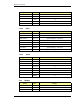
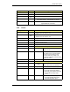
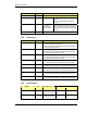
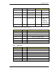
Table Of Contents
- Title
- Contents
- Introduction
- System Description
- Pre-Installation
- Receipt of Equipment
- Site Planning
- Main Rack and Supporting Hardware
- Remote ACUs
- RFUs
- RadioBlades
- RAPs
- URU
- Interconnecting Cabling
- Main Rack Configuration
- RF Planning
- Site Survey
- Alarm Configuration
- Tools Required
- Installation
- Equipment Commissioning
- iDEN Interface
- Power Plant
- RadioFrame System
- Coverage Validation
- Site Acceptance Guidelines
- RadioFrame System Functionality Test
- RadioFrame System iDEN Functionality Test
- Interconnect & Dispatch Setup & Voice Quality
- Packet Data Service Connection and Latency
- Short Message Service
- Handover and Cell Reselection
- Interconnect Connection Stability and SQE Performance
- Dispatch Connection Stability
- Idle SQE Testing and Validation
- System Self-Recovery Test
- Packet Data Stability and Throughput
- Validation of ‘Unable to Key BR’ Alarm
- Rectifier & AC Power Alarms
- iSC-3 Functionality Test
- RadioFrame System iDEN Functionality Test
- Connecting the RFS to the Customer LAN
- Operations and Maintenance
- Appendixes

Method of Procedure
Pre-Installation
36 RFN_3.1 Beta
System Unit Power
Output
Power Plant Rectifier Current
20 Amperes/Rectifier for 100/120
VAC
30 Amperes/Rectifier for 200/240
VAC
Output
Paralleling &
Hot Insertion
Each rectifier has an output o-ring diode
in the –48 VDC lead for the purpose of
paralleling and hot insertion in a working
system.
Battery 105ah; VRLA
3.3.5 Grounding
System Unit Grounding
Main Rack
#2 AWG green-insulated copper wire between the main
rack and the master ground bar
do not daisy-chain multiple equipment cabinet grounds
using a single ground wire
RadioFrame System NCU
internal grounding (UL and CE safety certified)
bonding point provided for protective earth grounding;
#8 screw with internal sems washer
ACU
internal grounding (UL and CE safety certified)
bonding point provided for protective earth grounding;
#8 screw with internal sems washer
iDEN Interface iSC-3 (1) #6 AWG ground wires are attached from the ground studs
on the rear of the iSC-3 to the cabinet ground bus bar
iSC-3 (2) #6 AWG ground wires are attached from the ground studs
on the rear of the iSC-3 to the cabinet ground bus bar
EAS #6 AWG ground wires are attached from the ground studs
on the rear of the EAS to the cabinet ground bus bar
CSU #6 AWG ground wires are attached from the ground studs
on the rear of the CSU to the cabinet ground bus bar
Power Plant Rectifier #6 AWG ground wires are attached from the ground studs
on the rear of the Rectifier to the cabinet ground bus bar
3.3.6 Environment
Operating Ambient Temperature System Unit Storage Temp
MIN MAX
RadioFrame System NCU* -40ºF to +158ºF
(-40ºC to +70ºC)
+32ºF (0ºC) +104ºF (+40ºC)
ACU* -40ºF to +158ºF
(-40ºC to +70ºC)
+32ºF (0ºC) +104ºF (+40ºC)