
Installation Guide
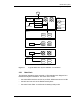
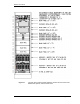
Table Of Contents
- Title
- Contents
- Introduction
- System Description
- Pre-Installation
- Receipt of Equipment
- Site Planning
- Main Rack and Supporting Hardware
- Remote ACUs
- RFUs
- RadioBlades
- RAPs
- URU
- Interconnecting Cabling
- Main Rack Configuration
- RF Planning
- Site Survey
- Alarm Configuration
- Tools Required
- Installation
- Equipment Commissioning
- iDEN Interface
- Power Plant
- RadioFrame System
- Coverage Validation
- Site Acceptance Guidelines
- RadioFrame System Functionality Test
- RadioFrame System iDEN Functionality Test
- Interconnect & Dispatch Setup & Voice Quality
- Packet Data Service Connection and Latency
- Short Message Service
- Handover and Cell Reselection
- Interconnect Connection Stability and SQE Performance
- Dispatch Connection Stability
- Idle SQE Testing and Validation
- System Self-Recovery Test
- Packet Data Stability and Throughput
- Validation of ‘Unable to Key BR’ Alarm
- Rectifier & AC Power Alarms
- iSC-3 Functionality Test
- RadioFrame System iDEN Functionality Test
- Connecting the RFS to the Customer LAN
- Operations and Maintenance
- Appendixes

RadioFrame System
System Description
RFN_3.1 Beta 19
Figure 11 A typical RadioFrame System iDEN/802.11b installation.
2.2.1 Main Rack
The following illustration shows a typical 19” EIA standard rack diagram for a
RadioFrame System installation. This main rack includes:
• the entire iDEN interface: two iSC-3s, an EAS, GPS Antennas and a CSU
• the NCU and one ACU of the RadioFrame System
• the entire Power Plant: 2 rectifiers and 8 battery backup units
NCU
ACU
ACU
Floor 4
GPS
To Remote ACUs
Floor 3
Sector 1
Legend
Sector 3
Sector 2
Floor 2
ACU
Floor 1
Parking
Level
iDEN
Interface
Power Plant
RFU 4
RFU 2
RFU 3
RFU 1
RFU 4
RFU 2
RFU 3
RFU 1
RFU 4
RFU 2
RFU 3
RFU 1
RFU 4
RFU 2
RFU 3
RFU 1
RFU 4
RFU 2
RFU 3
RFU 1
Customer
LAN
Main Rack