
Installation Guide
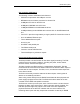
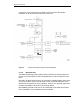
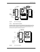
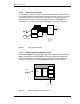
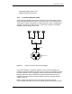
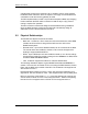
Table Of Contents
- Title
- Contents
- Introduction
- System Description
- Pre-Installation
- Receipt of Equipment
- Site Planning
- Main Rack and Supporting Hardware
- Remote ACUs
- RFUs
- RadioBlades
- RAPs
- URU
- Interconnecting Cabling
- Main Rack Configuration
- RF Planning
- Site Survey
- Alarm Configuration
- Tools Required
- Installation
- Equipment Commissioning
- iDEN Interface
- Power Plant
- RadioFrame System
- Coverage Validation
- Site Acceptance Guidelines
- RadioFrame System Functionality Test
- RadioFrame System iDEN Functionality Test
- Interconnect & Dispatch Setup & Voice Quality
- Packet Data Service Connection and Latency
- Short Message Service
- Handover and Cell Reselection
- Interconnect Connection Stability and SQE Performance
- Dispatch Connection Stability
- Idle SQE Testing and Validation
- System Self-Recovery Test
- Packet Data Stability and Throughput
- Validation of ‘Unable to Key BR’ Alarm
- Rectifier & AC Power Alarms
- iSC-3 Functionality Test
- RadioFrame System iDEN Functionality Test
- Connecting the RFS to the Customer LAN
- Operations and Maintenance
- Appendixes

RadioFrame System
System Description
RFN_3.1 Beta 13
Figure 5 NCU functional diagram.
2.1.2.2 Airlink Chassis Unit (ACU)
The Airlink Chassis Unit provides the baseband airlink processing for up to 8
RadioFrame Units, providing a coverage area up to 250,000 square feet. The
ACU is the interface between the RFUs and the Network Chassis Unit, and
provides power, signals, and timing to the RFUs.
Figure 6 ACU functional diagram.
AC-DC
Power
DLC
or
ALC
DLC
or
ALC
DLC
or
ALC
Control &
Encoded Voice
Data
CPU
RLIC
APC (1)
. . .
APC (8)
(Non-fully
configured)
DLC
or
ALC
Host I/F,
Encoded
Voice
Sys Config,
RF Control
Encoded
Voice
IS 41
Messaging
. . .
GU
PCM
DLC
Control &
Config
External
Mode
m
NPC
DSP Plug-In
DSP Plug-In
DSP Plug-In
DSP Plug-In
DSP Plug-In
DSP Plug-In
AC-DC
Power
4 “other”
LAN
Connections
AC-DC
Power
WLAN data, IQ
Samples, Clock,
Control, & Power
CPU
RIC
RFU (1)
. . .
RFN
LAN/WAN/
NCU
RFU (8)
WLAN Data,
Encoded Voice,
Layer 3
Messa
g
in
g
Host I/F,
IQ,
Encoded
Voice
IQ, WLAN
Data, Sys
Config, RF
Control
APC
DSP Plug-In
DSP Plug-In
AC-DC
Power