
Installation Guide
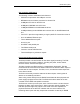
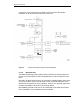
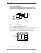
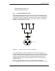
Table Of Contents
- Title
- Contents
- Introduction
- System Description
- Pre-Installation
- Receipt of Equipment
- Site Planning
- Main Rack and Supporting Hardware
- Remote ACUs
- RFUs
- RadioBlades
- RAPs
- URU
- Interconnecting Cabling
- Main Rack Configuration
- RF Planning
- Site Survey
- Alarm Configuration
- Tools Required
- Installation
- Equipment Commissioning
- iDEN Interface
- Power Plant
- RadioFrame System
- Coverage Validation
- Site Acceptance Guidelines
- RadioFrame System Functionality Test
- RadioFrame System iDEN Functionality Test
- Interconnect & Dispatch Setup & Voice Quality
- Packet Data Service Connection and Latency
- Short Message Service
- Handover and Cell Reselection
- Interconnect Connection Stability and SQE Performance
- Dispatch Connection Stability
- Idle SQE Testing and Validation
- System Self-Recovery Test
- Packet Data Stability and Throughput
- Validation of ‘Unable to Key BR’ Alarm
- Rectifier & AC Power Alarms
- iSC-3 Functionality Test
- RadioFrame System iDEN Functionality Test
- Connecting the RFS to the Customer LAN
- Operations and Maintenance
- Appendixes

Method of Procedure
System Description
10 RFN_3.1 Beta
connectors. These connectors are cabled to punch blocks to allow simple
installation of the remaining site alarm and control I/O.
Figure 3 Environmental Alarm System functional diagram.
2.1.1.2 GPS Antennas
The Global Positioning System (GPS) antenna provides the timing reference to
the iSC-3. One GPS antenna with a dedicated 50ohm coax is required for each
iSC-3.
Generally, the GPS antennas are to be mounted on a stable platform with a clear
view of the southern horizon and secured access. Horizontal separation of the
antennas is not required for proper operation; however, it is generally required to
increase survivability of the antenna from falling objects.
GPS satellite acquisition and lock can be verified with a handheld GPS receiver
prior to installation. Four satellites should be available.