
Installation Guide
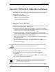
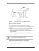
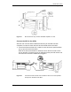

Table Of Contents
- Title
- Contents
- Introduction
- System Description
- Pre-Installation
- Receipt of Equipment
- Site Planning
- Main Rack and Supporting Hardware
- Remote ACUs
- RFUs
- RadioBlades
- RAPs
- URU
- Interconnecting Cabling
- Main Rack Configuration
- RF Planning
- Site Survey
- Alarm Configuration
- Tools Required
- Installation
- Equipment Commissioning
- iDEN Interface
- Power Plant
- RadioFrame System
- Coverage Validation
- Site Acceptance Guidelines
- RadioFrame System Functionality Test
- RadioFrame System iDEN Functionality Test
- Interconnect & Dispatch Setup & Voice Quality
- Packet Data Service Connection and Latency
- Short Message Service
- Handover and Cell Reselection
- Interconnect Connection Stability and SQE Performance
- Dispatch Connection Stability
- Idle SQE Testing and Validation
- System Self-Recovery Test
- Packet Data Stability and Throughput
- Validation of ‘Unable to Key BR’ Alarm
- Rectifier & AC Power Alarms
- iSC-3 Functionality Test
- RadioFrame System iDEN Functionality Test
- Connecting the RFS to the Customer LAN
- Operations and Maintenance
- Appendixes

RadioFrame System
Appendixes
RFN_3.1 Beta 149
Figure 37 Mount the ACU only in an EIA-standard compliant 19” rack.
Connect the NCU to the ACUs
After the main rack has been installed and all wiring for the RFS has been
completed, connect the main rack ACU and all remote ACUs to the NCU.
1 Connect the RJ45-to-RJ45 CAT 5 cable for each ACU to the specified RJ45
port (1-8) on the back of the NCU.
Refer to the site documentation to determine which ACU connects to each
port on the NCU. The Activity and Link LEDs above the ports will remain unlit
until each ACU has been installed and plugged in.
Figure 38 Connect the RJ45-to-RJ45 CAT 5 cable for each ACU to the specified
RJ45 port on the back of the NCU.