
Installation Guide

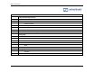
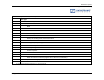
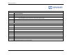
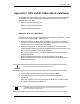
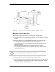
Table Of Contents
- Title
- Contents
- Introduction
- System Description
- Pre-Installation
- Receipt of Equipment
- Site Planning
- Main Rack and Supporting Hardware
- Remote ACUs
- RFUs
- RadioBlades
- RAPs
- URU
- Interconnecting Cabling
- Main Rack Configuration
- RF Planning
- Site Survey
- Alarm Configuration
- Tools Required
- Installation
- Equipment Commissioning
- iDEN Interface
- Power Plant
- RadioFrame System
- Coverage Validation
- Site Acceptance Guidelines
- RadioFrame System Functionality Test
- RadioFrame System iDEN Functionality Test
- Interconnect & Dispatch Setup & Voice Quality
- Packet Data Service Connection and Latency
- Short Message Service
- Handover and Cell Reselection
- Interconnect Connection Stability and SQE Performance
- Dispatch Connection Stability
- Idle SQE Testing and Validation
- System Self-Recovery Test
- Packet Data Stability and Throughput
- Validation of ‘Unable to Key BR’ Alarm
- Rectifier & AC Power Alarms
- iSC-3 Functionality Test
- RadioFrame System iDEN Functionality Test
- Connecting the RFS to the Customer LAN
- Operations and Maintenance
- Appendixes

Method of Procedure
Appendixes
148 RFN_3.1 Beta
Figure 36 Mount the NCU only in an EIA-standard compliant 19” rack.
Mount the ACU in the Main Rack
The ACU is mounted in the main rack supplied with –48VDC power.
1 Find these items in the ACU shipping container: one ACU and four mounting
screws.
2 Mount the ACU only in an EIA-standard compliant (19”) rack using all 4
screws provided. For safe operation, follow these guidelines:
• Do not mount the ACU in any orientation other than that specified in the
following illustration.
• Mount the ACU so that both the front and the back are accessible.
• If the mounting holes do not line up, adjust the ACU up or down until the
mounting holes line up.
Caution
Do not block the air vents on the sides or rear of the ACU.
3 Plug the ACU into main rack power source (rectifier or PDU).
4 Verify that the ACU is receiving power and that each NCU card is operational.
Each card installed in the front and back of the ACU has two LEDs: Power
and Status. All LEDs should light green.