
Installation Guide
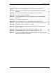
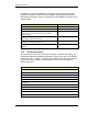
Table Of Contents
- Title
- Contents
- Introduction
- System Description
- Pre-Installation
- Receipt of Equipment
- Site Planning
- Main Rack and Supporting Hardware
- Remote ACUs
- RFUs
- RadioBlades
- RAPs
- URU
- Interconnecting Cabling
- Main Rack Configuration
- RF Planning
- Site Survey
- Alarm Configuration
- Tools Required
- Installation
- Equipment Commissioning
- iDEN Interface
- Power Plant
- RadioFrame System
- Coverage Validation
- Site Acceptance Guidelines
- RadioFrame System Functionality Test
- RadioFrame System iDEN Functionality Test
- Interconnect & Dispatch Setup & Voice Quality
- Packet Data Service Connection and Latency
- Short Message Service
- Handover and Cell Reselection
- Interconnect Connection Stability and SQE Performance
- Dispatch Connection Stability
- Idle SQE Testing and Validation
- System Self-Recovery Test
- Packet Data Stability and Throughput
- Validation of ‘Unable to Key BR’ Alarm
- Rectifier & AC Power Alarms
- iSC-3 Functionality Test
- RadioFrame System iDEN Functionality Test
- Connecting the RFS to the Customer LAN
- Operations and Maintenance
- Appendixes

Method of Procedure
Introduction
4 RFN_3.1 Beta
• Handle boards by the edges and avoid touching any conductive parts of the
board with your hands.
• Never remove a board with power applied to the unit (hot-pull) unless you
have verified it is safe to do so. Make sure the unit will not be damaged by
removing the board.
• Avoid carpeted areas, dry environments, and certain types of clothing (silk,
nylon, etc.) during service or repair due to the possibility of static buildup.
• Apply power to the circuit under test before connecting low impedance test
equipment (such as pulse generators, etc.). When testing is complete,
disconnect the test equipment before power is removed from the circuit under
test.
• Be sure to ground all electrically powered test equipment. Connect a ground
lead (-) from the test equipment to the board or module before connecting the
test probe (+). When testing is complete, remove the test probe first, and then
remove the ground lead.
• Place all boards and RadioBlades on a conductive surface (such as a sheet
of aluminum foil) when removed from the system. The conductive surface
must be connected to ground through 100kΩ.
• Never use non-conductive material for packaging boards or RadioBlades for
shipment or storage. All units should be wrapped with anti-static (conductive)
material. Replacement units shipped from the factory are packaged in a
conductive material.
• If possible, retain all original packing material for future use.
1.4 Safety Precautions
Read all the notices in this section prior to installing or using the RadioFrame
System or any of its components.
1.4.1 Safety Warnings
Warning!
Only trained and qualified personnel should be allowed to install, replace, or
service this equipment.
Warning!
This product relies on the building’s installation for short-circuit (over current)
protection. Ensure that a fuse or circuit breaker no larger than 120VAC, 15A U.S.
(240VAC, 10A international) is used on the phase conductors (all current-carrying
conductors).