
Installation Guide
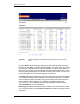
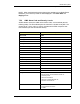
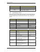

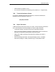
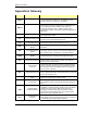
Table Of Contents
- Title
- Contents
- Introduction
- System Description
- Pre-Installation
- Receipt of Equipment
- Site Planning
- Main Rack and Supporting Hardware
- Remote ACUs
- RFUs
- RadioBlades
- RAPs
- URU
- Interconnecting Cabling
- Main Rack Configuration
- RF Planning
- Site Survey
- Alarm Configuration
- Tools Required
- Installation
- Equipment Commissioning
- iDEN Interface
- Power Plant
- RadioFrame System
- Coverage Validation
- Site Acceptance Guidelines
- RadioFrame System Functionality Test
- RadioFrame System iDEN Functionality Test
- Interconnect & Dispatch Setup & Voice Quality
- Packet Data Service Connection and Latency
- Short Message Service
- Handover and Cell Reselection
- Interconnect Connection Stability and SQE Performance
- Dispatch Connection Stability
- Idle SQE Testing and Validation
- System Self-Recovery Test
- Packet Data Stability and Throughput
- Validation of ‘Unable to Key BR’ Alarm
- Rectifier & AC Power Alarms
- iSC-3 Functionality Test
- RadioFrame System iDEN Functionality Test
- Connecting the RFS to the Customer LAN
- Operations and Maintenance
- Appendixes

Method of Procedure
Operations and Maintenance
130 RFN_3.1 Beta
Figure 35 Alarms are listed up to 200 at time and continue to scroll as events
occur.
For each Alarm, System Manager displays the alarm description and whether
the alarm is new (Set) or has been cleared (Clear). The same alarm will continue
to be listed as a set alarm until it has been cleared. If an alarm is not cleared, it
will be sent to the OMC (see “System Manager Alarm Descriptions” later in this
section). Other alarms might occur before an alarm clears, so the ‘set’ and ‘clear’
for the same alarm do not necessarily appear in sequence.
The Alarm Tag uniquely identifies each alarm using either the actual IP address
or hex digits to represent the IP address of the affected component. In the latter
case, the last four digits of the alarm tag represent the last two sets of digits of
the IP address of the component. For example, 0xc0a80679 represents
xxx.xxx.06.121. The IP address of the board generating the alarm is shown
under SrcAddress, or ‘source address’.
Board Type identifies which board within a chassis unit is affected (APC, CRIC,
etc.). For these alarms, select Click for chassis link to display the page for that
component.