
Installation Guide
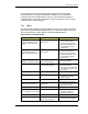
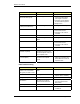
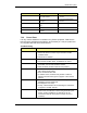
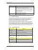
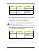
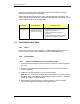
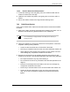
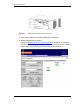
Table Of Contents
- Title
- Contents
- Introduction
- System Description
- Pre-Installation
- Receipt of Equipment
- Site Planning
- Main Rack and Supporting Hardware
- Remote ACUs
- RFUs
- RadioBlades
- RAPs
- URU
- Interconnecting Cabling
- Main Rack Configuration
- RF Planning
- Site Survey
- Alarm Configuration
- Tools Required
- Installation
- Equipment Commissioning
- iDEN Interface
- Power Plant
- RadioFrame System
- Coverage Validation
- Site Acceptance Guidelines
- RadioFrame System Functionality Test
- RadioFrame System iDEN Functionality Test
- Interconnect & Dispatch Setup & Voice Quality
- Packet Data Service Connection and Latency
- Short Message Service
- Handover and Cell Reselection
- Interconnect Connection Stability and SQE Performance
- Dispatch Connection Stability
- Idle SQE Testing and Validation
- System Self-Recovery Test
- Packet Data Stability and Throughput
- Validation of ‘Unable to Key BR’ Alarm
- Rectifier & AC Power Alarms
- iSC-3 Functionality Test
- RadioFrame System iDEN Functionality Test
- Connecting the RFS to the Customer LAN
- Operations and Maintenance
- Appendixes

Method of Procedure
Operations and Maintenance
122 RFN_3.1 Beta
Indication Corrective Action
Reset the breaker and measure the load through the
breaker using a current measuring device.
Does the current exceed 80% of the rating of the breaker?
If yes, remove and replace the breaker with a breaker that
meets the 80% rule.
Note: Maximum rating of the shelf is 30 amps and per CB
position is 30 amps.
Do not exceed the CB/plant ratings.
If current does not exceed 80% rating and breaker does not
trip, troubleshooting is complete.
7.3.3 RadioFrame System
RadioFrame Networks equipment and components are not field repairable. Do
not attempt to repair RFN equipment and components in the field. RFN
components are individually tested prior to shipment. Should a failure occur
replacement boards must be inserted and the RFS re-booted.
This section describes troubleshooting information for each component of the
RadioFrame System: NCU, ACU, RFU, and URU. If the provided solutions do
not resolve the problem, refer to the Field Guide to the RadioFrame System for
further troubleshooting information. If none of the provided solutions resolve the
problem, contact the Customer Assistance Center (TAC) at (425) 424-7620.
7.3.3.1 Network Chassis Unit
NCU front ports Description
Port 1 (RJ45) iSC—iDEN installations only
Port 2 (RJ45) Ethernet LAN—network installations only
Ports 3-8 (RJ45) additional Ethernet LANs
EIA-232 9-pin serial port for debugging—Customer Service use only
NCU back ports
Ports 1-8 (RJ45) ACUs—up to 8 ACUs may be connected to the NCU
5MHz/1PPs IN BNC connector for timing interface