
Installation Guide
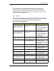
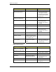
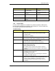
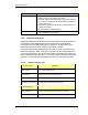
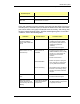
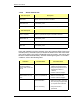
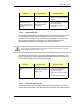
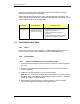
Table Of Contents
- Title
- Contents
- Introduction
- System Description
- Pre-Installation
- Receipt of Equipment
- Site Planning
- Main Rack and Supporting Hardware
- Remote ACUs
- RFUs
- RadioBlades
- RAPs
- URU
- Interconnecting Cabling
- Main Rack Configuration
- RF Planning
- Site Survey
- Alarm Configuration
- Tools Required
- Installation
- Equipment Commissioning
- iDEN Interface
- Power Plant
- RadioFrame System
- Coverage Validation
- Site Acceptance Guidelines
- RadioFrame System Functionality Test
- RadioFrame System iDEN Functionality Test
- Interconnect & Dispatch Setup & Voice Quality
- Packet Data Service Connection and Latency
- Short Message Service
- Handover and Cell Reselection
- Interconnect Connection Stability and SQE Performance
- Dispatch Connection Stability
- Idle SQE Testing and Validation
- System Self-Recovery Test
- Packet Data Stability and Throughput
- Validation of ‘Unable to Key BR’ Alarm
- Rectifier & AC Power Alarms
- iSC-3 Functionality Test
- RadioFrame System iDEN Functionality Test
- Connecting the RFS to the Customer LAN
- Operations and Maintenance
- Appendixes

RadioFrame System
Operations and Maintenance
RFN_3.1 Beta 119
Some indications list several possible failures along with corresponding
corrective actions. If a failure is isolated to the FRU level, the suspected
component should be replaced with a new one. This restores the system to
normal operation as quickly as possible. For more information, refer to section
7.6 Repair and Technical Support.
7.3.1 iSC-3
This section lists troubleshooting procedures for both the iSC-3 (site controller)
and the Environmental Alarm System (EAS). For further information, refer to the
Gen 3 Site Controller System Manual, Motorola, 68P80801E30-O.
Site Controller Troubleshooting
Indication Possible failure Corrective action
status gps MMI command
response: Satellite tracking
mode on all channels is less
than 8
Antenna, cables, surge
arrestors, RFI
Check antenna, cables, and
surge arrestors before
placing the site controller.
If antenna installation is OK,
suspect intermodulation
desensitizing.
status gps MMI command
response: S/N numbers of
mode 8 satellites are less than
25
Antenna, cables, surge
arrestors, RFI
Check antenna, cables, and
surge arrestors before
placing the site controller.
If antenna installation is OK,
suspect intermodulation
desensitizing.
ping gps MMI command
indicates no satellites tracked.
Open or damaged GPS and
surge satellites tracked.
Verify GPS antenna, lead-in,
and surge arrestor.
Slow handovers. Open or damaged GPS and
surge satellites tracked.
Verify GPS antenna, lead-in,
and surge arrestor.
Check for open 5 MHz cable
and missing termination of 5
MHz cable.
Power LED is not lit No power to site controller
Check power source
Cabling
Check power cabling to site
controller. If necessary,
replace cabling.
Site controller failure
Replace the site controller.
Site controller can’t
communicate over Ethernet
Ethernet cabling or
terminations
Check cabling. Verify that
each end of the cable has a
50-ohm termination.
Site controller failure
Replace the site controller.
LOS/OOF LED is lit
(Loss of Signal/Loss of Frame)
T1/E1 cabling
Check cabling to site
controller. If necessary,
replace the cabling.
Site controller failure
Replace the site controller.
Yellow Alarm LED is lit Site controller is receiving an
alarm from the far end.
Check for proper operation
of external site equipment.