
Installation Guide
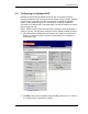

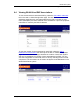
Table Of Contents
- Title
- Contents
- Introduction
- System Description
- Pre-Installation
- Receipt of Equipment
- Site Planning
- Main Rack and Supporting Hardware
- Remote ACUs
- RFUs
- RadioBlades
- RAPs
- URU
- Interconnecting Cabling
- Main Rack Configuration
- RF Planning
- Site Survey
- Alarm Configuration
- Tools Required
- Installation
- Equipment Commissioning
- iDEN Interface
- Power Plant
- RadioFrame System
- Coverage Validation
- Site Acceptance Guidelines
- RadioFrame System Functionality Test
- RadioFrame System iDEN Functionality Test
- Interconnect & Dispatch Setup & Voice Quality
- Packet Data Service Connection and Latency
- Short Message Service
- Handover and Cell Reselection
- Interconnect Connection Stability and SQE Performance
- Dispatch Connection Stability
- Idle SQE Testing and Validation
- System Self-Recovery Test
- Packet Data Stability and Throughput
- Validation of ‘Unable to Key BR’ Alarm
- Rectifier & AC Power Alarms
- iSC-3 Functionality Test
- RadioFrame System iDEN Functionality Test
- Connecting the RFS to the Customer LAN
- Operations and Maintenance
- Appendixes

Method of Procedure
Operations and Maintenance
118 RFN_3.1 Beta
Thermography (optional)
A thermal scan should be done on all AC components associated with the DC
power system.
Perform thermal scans on all battery and DC power connections, DC buss-work,
and circuit breakers.
7.2.3 Batteries
Conduct the following annual maintenance:
• Inspect Batteries: All cable connections and inter-cell connections. Check for
oxidation at terminal posts and clean as required.
• Check for leaks or seepage at terminal posts and battery jar seals.
• Replace the battery jar if any leak or seepage.
• Torque battery terminal and strap connections nuts and bolts to
manufacturer’s specifications. Power Battery CSL-12100 Specification is 115
in/lbs.
• Verify battery voltage and mid-point voltage.
• Perform Midtronics battery analysis using digital battery analyzer (optional).
7.2.4 RadioFrame System
Conduct the following semi-annual maintenance:
• Visually inspect all RFS components for loose or foreign items and for visible
damage.
• Confirm that each component is receiving power (refer to the troubleshooting
tables listed in 7.3 Corrective Maintenance, next in this chapter).
• Verify that all RFS components are operational (refer to section 5.3.1.2
Checking the Status of RFS Components).
• Verify coverage validation by conducting spot tests described in section 5.4
Coverage Validation.
• Verify iDEN functionality by conducting spot tests using the procedures
described in section 5.6 RFS Functionality Test.
7.3 Corrective Maintenance
The fault indications identified in this section provide a guide for isolating failures
to a Field Replaceable Unit (FRU). The service technician should perform
troubleshooting whenever a failure occurs during normal operation that cannot be
resolved by the Operations and Maintenance Center (OMC).