
Installation Guide
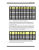
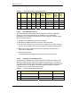
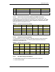
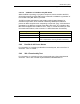
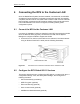
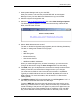
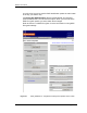
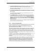
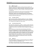
Table Of Contents
- Title
- Contents
- Introduction
- System Description
- Pre-Installation
- Receipt of Equipment
- Site Planning
- Main Rack and Supporting Hardware
- Remote ACUs
- RFUs
- RadioBlades
- RAPs
- URU
- Interconnecting Cabling
- Main Rack Configuration
- RF Planning
- Site Survey
- Alarm Configuration
- Tools Required
- Installation
- Equipment Commissioning
- iDEN Interface
- Power Plant
- RadioFrame System
- Coverage Validation
- Site Acceptance Guidelines
- RadioFrame System Functionality Test
- RadioFrame System iDEN Functionality Test
- Interconnect & Dispatch Setup & Voice Quality
- Packet Data Service Connection and Latency
- Short Message Service
- Handover and Cell Reselection
- Interconnect Connection Stability and SQE Performance
- Dispatch Connection Stability
- Idle SQE Testing and Validation
- System Self-Recovery Test
- Packet Data Stability and Throughput
- Validation of ‘Unable to Key BR’ Alarm
- Rectifier & AC Power Alarms
- iSC-3 Functionality Test
- RadioFrame System iDEN Functionality Test
- Connecting the RFS to the Customer LAN
- Operations and Maintenance
- Appendixes

RadioFrame System
Equipment Commissioning
RFN_3.1 Beta 99
Table 3 Private Dispatch Call Quality, Setup, and Stability
Test
#
MO/MT Carrier # RSSI
(dbm)
SQE
(dbm)
Quality
(1-5)
Distance
(ft)
Sector Duration
(Min)
1 50 2:30
2 50 2:30
3 50 2:30
4 50 2:30
5 50 2:30
6 50 2:30
7 50 2:30
8 50 2:30
9 50 2:30
10 50 2:30
5.6.1.2 Packet Data Service Connection and Latency
The Packet Data service will be tested and verified on the RadioFrame System.
Motorola’s Packet Data Applet will be used to connect to the RFN customer’s
Packet Data network over the RadioFrame System, using a tethered connection
with a Motorola handset.
Several samples of PING requests will be sent to a Router in the RFN customer’s
Packet Data network and average round trip times will be recorded to measure
latency. The table below presents the data to be collected for each ping using the
RFS. These tests shall be performed using Windows 2000 OS and the timeout
for each ping reply shall be set to 2000 milliseconds.
Table 4 Packet Data Latency over the RFS (Ping –n 100 –w 2000
xx.xxx.xxx.x )
T
est # Handset Carrier # RSSI
(dbm)
SQE
(dbm)
Ping
(No. of
Echos)
Router (IP
Address)
Average
Round
Trip Time
(msec)
Packet
Loss
(%)
1 100 xxx.xxx.xxx.x
2 100 xxx.xxx.xxx.x
3 100 xxx.xxx.xxx.x
4 100 xxx.xxx.xxx.x
5 100 xxx.xxx.xxx.x
The following table presents (baseline) data collected for each ping using a
Motorola Macrocell in order to average Round Trip time over the RFS versus
over Motorola standard Base Station equipment.