
User's Manual


RadioFrame System Method of Procedure GSM/802.11b
Operations and Maintenance
92 RadioFrame Networks, Inc.
4 Place the old board in the antistatic packaging for shipment.
5 Restart the RadioFrame System.
Select the Software Download & System Reset
link located at the bottom of the BCU
configuration page, and select the “Reset System” button to cause a system reset.
The reboot may take several minutes to complete.
7.5 Alarm Resolution Procedures
The RFS provides fault alarming and isolation within System Manager for individual
components, which consists of detecting catastrophic faults that prevent an RFS
component from responding to a periodic “ping”.
This section describes:
• How to view alarms in System Manger, and
• System Manager alarms and resolution procedures.
7.5.1 Viewing System Manager Alarms
System Manager displays system-related errors.
1
To view alarms and other system-related errors in System Manager, select the
Alarms tab.
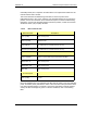
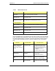
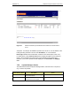
The Alarms Log displays RFS alarms, listed by Time of occurrence (including the
date), in a sequence of 400 alarms at a time—No. (see the following illustration).
Approximately 25 alarms are visible at any one time. At the bottom of the page, you
can see which alarms are currently displayed, in this case, 99 through 118 of 118
alarms.
NOTE: If the Alarms page is empty, System Manager is still loading the page.
2
To display alarms that have scrolled out of view, select first, prev, next, last or all at
the bottom of the alarm page, then enter a value in the Show text box and press
enter.
For example, to view the first 20 alarms, click first and type 20 in the text box, then
press Enter. To return to the bottom of the list of alarms, select last and type a value
in the text box.
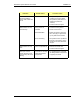
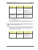
For each Alarm, System Manager displays the alarm description and whether the alarm
is new (Set) or has been cleared (Clear). The same alarm will continue to be listed as a
set alarm until it has been cleared. If an alarm is not cleared, it will be sent to the OMC
(see “System Manager Alarm Descriptions” later in this section). Other alarms might
occur before an alarm clears, so the ‘set’ and ‘clear’ for the same alarm do not
necessarily appear in sequence.
The Alarm Tag uniquely identifies each alarm using either the actual IP address or hex
digits to represent the IP address of the affected component. In the latter case, the last
four digits of the alarm tag represent the last two sets of digits of the IP address of the