
User's Manual


GSM/802.11b RadioFrame System Method of Procedure
Operations and Maintenance
RadioFrame Networks, Inc.
91
7.4 Field Replaceable Units
In the case of chassis units, replacement boards must be inserted and the RFS re-
booted.
1
Always use a static grounding wrist strap before handling any board—do not attach
the wrist strap to any painted surface on the chassis unit.
Note
It is not necessary to unplug the BCU or the ACU prior to removing or
inserting a board.
2 Facing the chassis unit, remove the card that is to be replaced, or the blank
faceplate, following these guidelines:
· Loosen the blue knurled knobs on both sides of the board.
· Pull firmly to unseat the board from the connectors inside the chassis unit.
· Gently slide the board straight out and away from the chassis unit so as not to
damage any components contained on the board.
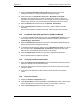
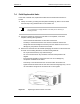
3 Remove the new board from its antistatic packaging and insert it into the chassis unit
as shown in the following illustration, and follow these guidelines:
· Do not jam the board in any way while inserting it.
· Do not mount the board in any orientation other than that specified in the
diagram.
· Insert the board straight into the chassis unit so as not to damage any
components contained on the board.
· Press firmly to seat the board into the connectors within the chassis unit.
· Tighten the blue knurled knobs on each end of the board finger tight only—do not
use a screwdriver to tighten the screws and do not over tighten.
Figure 21 Replacing a board in a BCU or an ACU.