
User's Manual


GSM/802.11b RadioFrame System Method of Procedure
Operations and Maintenance
RadioFrame Networks, Inc.
89
7.3.1.2 Airlink Chassis Unit
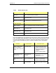
ACU front ports Description
RJ45 Port 1 BCU—connects the ACU to the BCU
RJ45 Ports 2-8 not currently used
EIA-232 9-pin serial port for maintenance—Customer Service use only
ACU back ports
Ports 1-8 (RJ45) RFUs—up to 8 RFUs may be connected to the ACU
5MHz/1PPs IN not currently used
5MHz/1PPs OUT not currently used
GPS ANT not currently used
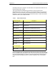
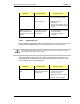
Each card installed in the front and back of the ACU has two LEDs: Power (top) indicates
power, and Status (lower) indicates the status of the card. Each RJ45 port has two LEDs:
Link (right) indicates Ethernet connectivity, and Activity (left) blinks to indicate Ethernet
activity. All LEDs should light as green. For all other conditions, refer to the following
table.
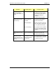
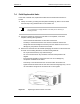
Indication Possible failure Corrective action
Power or Status LEDs
for cards installed in
front or back of ACU are
not lit
no power to ACU
Verify that the power cord is
installed and properly seated.
Verify that the power source is
operational (120VAC or
–48VDC).
Contact Customer Support.
Status LED is red—top
front card only
timing source not
available
Connect the timing source. In
some cases.
Check all connections.
Status LED is red—any
card
card is not operational
Remove and reseat card.
Contact Customer Support.
failed initialization
Reboot the system: unplug the