
User's Manual


GSM/802.11b RadioFrame System Method of Procedure
Operations and Maintenance
RadioFrame Networks, Inc.
87
individually tested prior to shipment. Should a failure occur replacement boards must be
inserted and the RFS re-booted.
This section describes troubleshooting information for each component of the
RadioFrame System: BCU, ACU, and RFU. If the provided solutions do not resolve the
problem, refer to the Field Guide to the RadioFrame System for further troubleshooting
information. If none of the provided solutions resolve the problem, contact the Customer
Assistance Center (TAC) at (800) 328-0847.
7.3.1.1 Base Chassis Unit
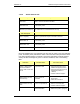
BLIC front ports Description
Port 1 (RJ45) Not currently used
Port 2-7 (RJ45) Ethernet LAN
Ports 8 (RJ45) for maintenance—Customer Service use only
EIA-232 9-pin serial port for maintenance—Customer Service use only
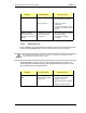
BLIC back ports
Ports 1-8 (RJ45) ACUs—up to 8 ACUs may be connected to the BCU
5MHz/1PPs IN Not currently used
5MHz/1PPs OUT Not currently used
GPS ANT Not currently used
DLC back ports
Port 1 (RJ45) T1/E1
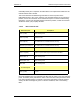
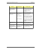
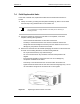
Each card installed in the front and back of the BCU has two LEDs: Power (top) indicates
power, and Status (lower) indicates the status of the card. Each RJ45 port has two LEDs:
Link (right) indicates Ethernet connectivity, and Activity (left) blinks to indicate Ethernet
activity. All LEDs should light as green. For all other conditions, refer to the following
table.