
User's Manual


GSM/802.11b RadioFrame System Method of Procedure
Final Checkout
RadioFrame Networks, Inc.
67
5.4 Coverage Validation
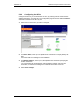
After configuring all RFS components, use measurement software, a laptop and a GSM
handset to check for regions of low signal strength or low signal quality (RXQUAL).
5.4.1 Detailed Building Plans—RF Modeling
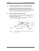
Testing by RFN has shown that simple Linear Attenuation Models (LAM) as discussed in
COST 231, Chapter 4 section 4.7 “Indoor Propagation Models” work well when used on a
floor-by-floor basis. An attenuation coefficient of 0.62dB/m is recommended for dense,
single-floor propagation, but this can double if concrete walls are present.
5.4.2 Measurement-based Estimate
A battery-powered test transmitter can be moved between each proposed RFU location
and a handheld signal strength meter used to monitor RSSI. This method is useful when
RF penetration is desired through suspect walls or where wall construction data is
lacking. Generally, this method provides good agreement when used to identify regions
of poor coverage rather than to establish sufficient coverage zones. This is because it is
usually inconvenient to duplicate an RFUs’ position during initial coverage surveys.
5.4.3 Floor Plan Estimate
Oftentimes, only simple floor plans are available for the building in which the RFUs are to
be installed. Without specifics about the building construction, such as interior wall, floor
and ceiling construction, propagation models are of limited value. A measurement-based
approach (discussed earlier) works well, but for simple buildings, installing RFUs at the
candidate locations and then testing the results will likely be adequate. If regions of poor
coverage are found, additional RFUs may be added.
5.5 Site Acceptance Guidelines
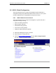
5.5.1 Site As-Built Documentation
As-built documentation consists of the original site development documentation with post-
installation information. On the job, installers use site development documentation for
reference, to make notes, and to document completion of each step of the installation.
Conduct an onsite walk through to verify that the following Site Development Punch List
items have been properly installed. This inspection ensures that the site installation
meets quality standards.
• Grounding
- buss bar OK (optional)
- BCU/ACU rack(s)
• T1/E1 Information, Primary and Secondary
- T1/E1 circuit ID#
- T1/E1 surge arrestor installed/grounded