
User's Manual


GSM/802.11b RadioFrame System Method of Procedure
Final Checkout
RadioFrame Networks, Inc.
57
5 Final Checkout
The procedures in this chapter describe how to conduct commissioning and system test
procedures for the GSM/802.11 RadioFrame System. Following the successful
completion of procedures described in this chapter, the RFS can be connected to the
customer LAN as described in Chapter 6 “Connecting the RFS to the Customer LAN”.
The procedures in this chapter are to be used in conjunction with troubleshooting and
repair information provided in Chapter 7 Operations and Maintenance and the RFN
document, Field Guide to the RadioFrame System. Together, these troubleshooting
solutions and commissioning procedures provide the necessary information to isolate
failures to a Field Replaceable Unit (FRU). This minimizes system downtime by quickly
returning the site to normal operation.
This chapter’s procedures check system functions and help isolate failures down to the
FRU level. If a failure cannot be isolated after performing these tests, refer to Chapter 1
“Repair and Technical Support” for technical assistance information.
5.1 Start System Manager
After installation of all RadioFrame Networks equipment, including verification that each
unit is receiving power, start System Manager to complete the installation of the
RadioFrame System. System Manager automatically downloads information about each
component in the RFS, including assigned IP addresses, sector information, port
connections, and component status, as well as specifying default information that can be
changed, or ‘configured’.
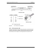
1
Using a 9-pin serial cable, connect a laptop computer to the RS232 port on the front
of the BCU.
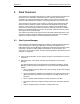
2
Start the browser on the laptop, and enter the provided URL to start System
Manager.
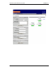
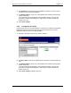
The System Manager Home page appears (see the following illustration). System
Manager contains five tabs you select from to set up and monitor the RadioFrame
System:
• Home—displays a welcome banner and a link for setting up users and changing
the RFS password.
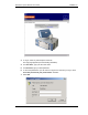
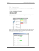
• System Configuration—displays the configuration of each RFS component, and
depicts the location and status of each component, including the BCU, ACUs,
and RFUs.
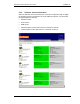
• Alarms—displays alarm information for each component of the RFS.
• Performance Monitoring—displays real-time performance information about the
RFS.
• Support—displays support information, including online help.