
User's Manual


GSM/802.11b RadioFrame System Method of Procedure
Installation
RadioFrame Networks, Inc.
55
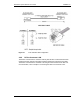
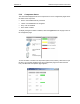
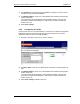
Figure 18 Slide each GSM RadioBlade into the specified slot in the RFU.
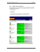
6 Insert the 802.11b/g iRAPs, one at a time, into the specified slots in the RFU until the
connector on each iRAP seats firmly into the back of the RFU (see the following
illustration).
7 Remove the antistatic wrist strap and place the front cover on the RFU.
4.4 Interconnecting Cabling
4.4.1 T1/E1
The Telco interface should have been installed according to the Pre-installation chapter.
NOTE: The equipment can be installed and tested without the Telco T1/E1 present. The
T1/E1 must be connected for proper operation of the site.
NOTE: Some modular cables have a ridge along one side of the cable for purposes of
alignment with the connector.
NOTE: The SmartJack is capable of passing -48V Telco power through to the site
controller. For operation, GSM does not require this power. If -48V is present on the
network connection to the site controller, the SmartJack is incorrectly configured. Contact
the service provider immediately to correct this situation. The SmartJack switch should be
set so that -48V power does not pass through to the site controller.
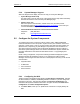
If this cable is locally manufactured, crimp the 8-pin connectors as shown in the following
illustration. The wires should be routed straight through. Make sure that the conductor
color is the same at both ends for each conductor of the cable.