
User's Manual


RadioFrame System Method of Procedure GSM/802.11b
Installation
52 RadioFrame Networks, Inc.
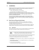
4.3.1.1 Wall Mount
1
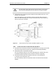
Place the 11” x 17” drawing template (P/N 981-1020-00) on the wall where the
RadioFrame Unit is to be mounted.
2 Mark the two locations indicated on the template.
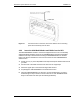
3 Screw the two supplied anchors into the locations as shown in the following diagram.
4 Screw the two supplied screws into the anchors, leaving approximately 1/4” of each
screw exposed.
5 Hang the RFU on the anchors and fully tighten both screws.
Figure 15 A wall mount requires two screws to anchor the RFU.
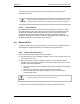
4.3.1.2 Ceiling Mount
1
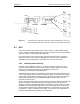
Place the 8.5” x 11” drawing template (P/N 981-1010-00) on the ceiling where the
RFU is to be mounted.
2 Mark the four locations indicated on the template.
3 Drill four holes with the appropriately sized bit: 3/16” for the provided wood screws, or
9/32” for 1/4” bolts (bolts not provided).
If using the provided wood screws, ensure that all four screws penetrate wood.
Otherwise, use alternative mounting screws or bolts to secure the ceiling bracket.
4 Using four screws or bolts, attach the ceiling bracket to the ceiling as shown in the
following diagram.
5 Attach the RFU to the ceiling mount bracket and fully tighten the thumbscrew.