
User's Manual


RadioFrame System Method of Procedure GSM/802.11b
Installation
50 RadioFrame Networks, Inc.
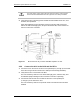
Caution
The power supply cord is used as the main disconnect device; ensure that the
socket-outlet is located/installed near the equipment and is easily accessible.
4 Verify that the ACU is receiving power and that all cards installed in the ACU, front
and back, are operational.
Each card installed in the front and back of the ACU has two LEDs: Power and
Status. All LEDs should light green, except for the Status LED, which remains red
until the T1/E1 line is connected.
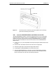
Figure 13 Mount the ACU only in an EIA-standard compliant 19” rack.
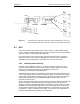
4.2.2 Connect the ACU to the BCU and the RFUs
1
Connect Port 2 on the front of the ACU to the specified port (1 through 8) on the back
of the BCU using an RJ45-to-RJ45 CAT-5 cable (see the following illustration).
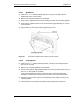
2
Verify that the ACU is connected to the BCU.
The Link and Activity LEDs on Port 2 should both light green, and the Activity LED
should blink rapidly indicating that the connection to the BCU is operating.
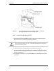
3
Connect the RJ45-to-RJ45 CAT-5 cable for each RFU to the specified port
(1 through 8) on the back of the ACU.
The Link and Activity LEDs on the ports will remain unlit until each RFU has been
installed.