
User's Manual


RadioFrame System Method of Procedure GSM/802.11b
Installation
48 RadioFrame Networks, Inc.
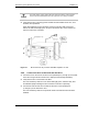
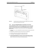
5 Remove the four screws securing the bottom kick panel to the front and back of the
main rack.
Remove the kick panel and set aside during installation.
6 Carefully move the main rack into the position indicated by the holes in the floor.
Adjust and level the main rack as necessary to align the rack mounting holes with the
pre-drilled holes in the floor.
7 Secure the main rack to the site floor with the locally procured mounting hardware.
8 If required, connect adjacent cabinets to each other using ganging hardware.
4.1.2 Auxiliary Equipment
Auxiliary equipment for the main rack includes:
• Surge arrestors
• Grounding
• Cable supports
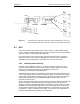
4.1.2.1 Surge Arrestors
T1/E1
The T1/E1 surge arrestor must be adequately grounded. The surge arrestor usually
mounts near the demarcation (demarc) point. The cable connecting the surge arrestor to
the Telco SmartJack should be locally procured, or should be provided with the surge
arrestor.
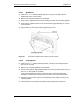
AC power (optional)
An RFN-approved surge arrestor must be installed adjacent to the AC power panel. Very
short wire lengths between the arrestor and the power panel are required for proper
operation of equipment.
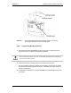
4.1.2.2 Grounding
Within the site, ground the main rack with a single dedicated connection between the
main rack and the master ground bar. The connecting wire must be a #2 AWG green-
insulated copper wire.
Use appropriate lugs (and split ring lock washers when possible) with an anti-oxidant
grease applied for interior grounding connections and exterior secondary grounding
connections. If lock washers are used, they should be placed between the nut and the lug
to ensure the mechanical integrity of the connection. The washer must not be secured
between the lug and the surface to which it is connected. Painted connections must be
scraped clean before applying the anti-oxidant grease and lug.