
User's Manual


GSM/802.11b RadioFrame System Method of Procedure
Pre-Installation
RadioFrame Networks, Inc.
39
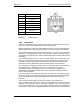
Wire Connection
-48 Volts DC Return (black)
-48 Volts DC (red)
Caution
The power supply cord is used as the main disconnect device for the chassis unit.
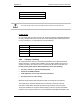
Length of run
For runs longer than nine feet, use only a UL-approved cable (the suggested standard is
UL1007), with approved connectors as shown in the following table. Wire shall be sized
to carry a minimum of 11 Amps per these recommendations:
Length of Run Minimum recommended wire gauge
Up to 6’ 16 AWG
6’ - 10’ 14 AWG
10’ - 15’ 12 AWG
15’ - 24’ 10 AWG
3.8.3 Category 5 Cabling
All components of the RFS are connected using standard CAT-5 cabling installed in
existing raceways or conduits when available. Use only RJ45 (T568B) connectors for
system components. The same is true for connecting the RFS to the Customer LAN.
If using a patch panel between RFS components, ensure the following:
• Use only a CAT-5e- or CAT-6-rated patch panel.
• Follow all TIA 568B standards.
• Total impedance, end to end, cannot exceed 8 ohms.
• Use only CAT-5e or CAT-6 wiring.
Maximum length between RFS components shall not exceed 328’ (100 meters).
The maximum DC resistance allowed cannot exceed 26.2 Ohms per 1000 feet.
Use plenum rated cable if the cable traverses through a plenum (open air) space.
The proper installation of computer network cabling is critical to the safe and reliable
operation of the computer network. It is recommended that standards developed by the