
User's Manual


GSM/802.11b RadioFrame System Method of Procedure
Pre-Installation
RadioFrame Networks, Inc.
29
Insulated standoffs are recommended for use in racks or cabinets. The standoffs should
be of sufficient length to maintain the proper cable separation.
Nonmetallic cable ties shall be used to secure cables and conductors. Attachment shall
be tight enough to secure cables without crushing them.
Cables that span a gap greater than 2 ft (61 cm) shall be supported.
3.3.9.2 Routing cables within racks and cabinets
Grounding conductors within racks or cabinets shall be routed toward the RGB, MGB,
SSGB, or ground bus conductor. Connections to the RGB or ground bus conductor shall
always be made with the equipment grounding or tap conductors being routed toward the
MGB, SSGB, or RGB.
At points where grounding conductors must pass through a hole in a metallic surface and
the hole is slightly larger than the conductor, the conductor shall be bonded to the
metallic surface through which it passes. If the hole or opening is much larger than the
conductor, and it is intended to accommodate several conductors, the conductor is not
required to be bonded.
Cables in racks or cabinets shall be sized to length, and shall be installed and routed
neatly and in a professional manner.
Excess cable shall not be coiled on top of cabinets or racks.
AC power cords longer than necessary may be looped down and back up a
rack or
cabinet. Excess lengths of AC power cord shall not be coiled on top of racks or cabinets.
3.3.9.3 Protecting cables within racks and cabinets
Grounding conductor tap joints shall be installed in order to prevent the conductor or
connection device from coming in contact with metallic surfaces.
Where cables or conductors are routed through holes in metallic surfaces or near sharp
edges, the sharp surfaces shall be suitably protected with a grommet or similar material
to help protect the cable or conductor from damage caused by sharp edges.
3.3.9.4 Cable bending radius within racks and cabinets
Grounding conductors of all sizes shall maintain a minimum bending radius of 8 in. (20
cm). The angle of any bend shall be not less than 90°.
The bending radius of CAT-5 cables shall be not less than 10 times the outside diameter
of the cable. Follow the cable manufacturer's recommendation and refer to
ANSI/TIA/EIA-568 and CSA-T529 for additional information.
All other cables shall not have sharp bends that will damage or degrade the performance
of the cable. The cable manufacturer's specifications shall be followed.
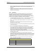
3.3.9.5 Cable separation and grouping within racks or cabinets
Cabling in racks or cabinets shall be grouped according to function.