
User's Manual


RadioFrame System Method of Procedure GSM/802.11b
Pre-Installation
28 RadioFrame Networks, Inc.
3.3.8 Surge Arrestors
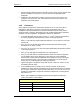
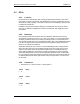
The local telephone company installs the T1/E1 line, which terminates in an 8-pin
modular plug. This demarcation (demarc) point connects to the T1/E1 through a surge
arrestor. The following illustration shows the T1/E1 interface with the GSM/802.11b/g
RFS.
Figure 11 Telco (T1/E1) interface with the GSM/802.11b/g RFS.
The surge arrestor must be adequately grounded. The surge arrestor usually mounts
near the demarcation (demarc) point. The cable connecting the surge arrestor to the
Telco SmartJack should be locally procured, or should be provided with the surge
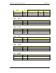
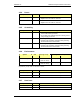
arrestor. The following table lists RFN-approved surge suppression equipment.
AC Data Part # Application Clamp Voltage
TJ1010B T1/E1 Surge Suppression, SAD + Gas Tube Hardwire
and/or RJ connection
10 V
TJ3010B T1/E1 Surge Suppression, SAD + Gas Tube Hardwire 7 V
3.3.9 Cable Support
This section describes requirements for cabling within equipment cabinets and racks.
Cabling within racks and cabinets shall conform to the requirements of NFPA 70, Article
300, Article 800, Article 810, and Article 820. (Refer to ANSI/TIA/EIA-568(a) and 569(a)
for additional information.)
All cables shall be installed and routed so that personal safety and equipment
functionality is not compromised and that all equipment is accessible for servicing. The
following requirements apply to cabling installed in racks or cabinets.
3.3.9.1 Securing cabling within racks or cabinets
To help prevent damage or accidental disconnection, cables and conductors shall be
secured at intervals of no more than 3 ft (91 cm). Attachment shall be accomplished in a
manner that does not restrict access to the equipment in the rack or cabinet.