
User's Manual

RadioFrame System Method of Procedure GSM/802.11b
System Description
10 RadioFrame Networks, Inc.
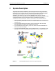
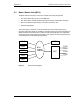
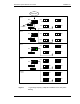
2.2 Airlink Chassis Unit (ACU)
The Airlink Chassis Unit provides the baseband airlink processing for up to 8 RadioFrame
Units. The ACU is the interface between the RFUs and the Base Chassis Unit, and
provides power, signals, and timing to the RFUs.
Figure 3 ACU functional diagram.
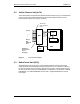
2.3 RadioFrame Unit (RFU)
The RadioFrame Unit serves as the access interface between signals received from
mobile terminals and the airlink processing performed in the ACU. The RFU connects to
the ACU via a single CAT-5 connection, and receives its power, signals, and timing from
the ACU. Each RFU holds up to 6 RadioBlades in combination of: a maximum of 6 GSM
RadioBlades, or 4 GSM RadioBlades and one 802.11 integrated RadioFrame Access
Point (RAP).
A
C
-
DC
Powe
WLAN data,
Clock, Control &
Power
CPU
RIC
RFU (1)
. .
.
RFN
LAN/WAN/
BCU
RFU (8)
WLAN Data,
Encoded Voice,
Layer 3
Messaging
WLAN
Data, Sys
Config, RF
Control
APC
DSP Plug
-
In
DSP Plug
-
In
A
C
-
DC
Powe
r