
User's Manual

RadioFrame System Method of Procedure GSM/802.11b
System Description
8 RadioFrame Networks, Inc.
2 System Description
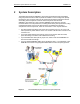
The RadioFrame Networks GSM/802.11b/g solution generates RF within the building
using low-power transceivers that are placed as needed to meet coverage and capacity
requirements. The low-power nature of the transceivers minimizes interference with the
surrounding macrocell system so that the macrocell system views the RFN
GSM/802.11b/g solution as a peer. The RFN GSM/802.11b/g solution is remotely
monitored down to the component level, including alarms and system performance, using
a web-based interface, and over the Abis interface. The RadioFrame System is
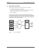
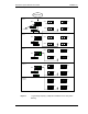
comprised of several components, which are connected in a ‘tree’-style architecture:
• The Base Chassis Unit (BCU) acts as the sole connection point (i.e. the ‘root’) to all
ACUs (and RFUs) which ‘branch’ off this ‘root’ chassis. The BCU also connects to the
customer LAN.
• Up to eight Airlink Chassis Units (ACUs) connect from the BCU and send traffic,
power and timing to the RFUs over standard CAT-5 wiring.
• Up to 64 RadioFrame Units (RFUs), 8 per ACU, which house the RadioBlades are
mounted on walls and ceilings.
• Up to six GSM RadioBlades (RBs) can be installed per RFU, or a combination of four
GSM RBs and one 802.11b/g integrated RadioFrame Access Point (RAP) per RFU.
Figure 1 The RadioFrame System uses a ‘tree’-style architecture.