
User's Manual

RadioFrame System Method of Procedure GSM/802.11b
Appendix C: BCU and ACU Main Rack Installation
106 RadioFrame Networks, Inc.
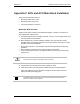
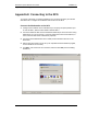
Figure 23 Mount the BCU only in an EIA-standard compliant 19” rack.
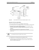
Mount the ACU in the Main Rack
The ACU is mounted in the main rack supplied with –48VDC power.
1
Find these items in the ACU shipping container: one ACU and four mounting screws.
2
Mount the ACU only in an EIA-standard compliant (19”) rack using all 4 screws
provided. For safe operation, follow these guidelines:
• Do not mount the ACU in any orientation other than that specified in the following
illustration.
• Mount the ACU so that both the front and the back are accessible.
• If the mounting holes do not line up, adjust the ACU up or down until the mounting
holes line up.
Caution
Do not block the air vents on the sides or rear of the ACU.
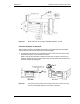
3
Plug the ACU into main rack power source (rectifier or PDU).
4
Verify that the ACU is receiving power and that each BCU card is operational.
Each card installed in the front and back of the ACU has two LEDs: Power and
Status. All LEDs should light green.