RadioFrame Networks RadioFrame System Method of Procedure GSM/802.
RadioFrame System Method of Procedure GSM/802.11b Service Information This equipment complies with part 15 of the FCC Rules. Operation is subject to the two following conditions: This device may not cause harmful interference, and this device must accept any interference received, including interference that may cause undesired operation. This equipment has been tested and found to comply with the limits pursuant to part 90.691 of the FCC Rules.
GSM/802.11b RadioFrame System Method of Procedure Contents 1 Introduction ............................................................................................................... 1 1.1 1.2 1.3 2 System Description................................................................................................... 8 2.1 2.2 2.3 2.4 2.5 2.6 2.7 3 Receipt of Equipment .................................................................................... 18 Site Planning ..............................
RadioFrame System Method of Procedure 5.5 5.6 6 Site Acceptance Guidelines........................................................................... 67 RadioFrame System Functionality Test......................................................... 70 Connecting the RFS to the Customer LAN ........................................................... 71 6.1 6.2 6.3 6.4 6.5 7 GSM/802.11b Connect the BCU to the Customer LAN ........................................................ 71 802.
GSM/802.11b RadioFrame System Method of Procedure List of Figures Figure 1 The RadioFrame System uses a ‘tree’-style architecture. ............................ 8 Figure 2 BCU functional diagram................................................................................ 9 Figure 3 ACU functional diagram.............................................................................. 10 Figure 4 GSM RadioBlade functional diagram. ........................................................
RadioFrame System Method of Procedure Figure 25 vi GSM/802.11b Connect the RJ45-to-RJ45 CAT-5 cable from Port 2 on the front of the ACU to the specified RJ45 port on the back of the BCU. ......................... 107 RadioFrame Networks, Inc.
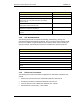
GSM/802.11b RadioFrame System Method of Procedure Introduction 1 Introduction 1.1 Scope of the Manual This manual describes standards for installing, modifying and maintaining RadioFrame Networks’ equipment at RadioFrame Networks customer sites. All specifications and requirements pertain to the RadioFrame Networks equipment required in Global System for Mobile communications (GSM)/802.11b/g installations.
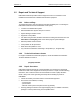
RadioFrame System Method of Procedure GSM/802.11b Introduction Task Responsible Party Prepares system design and quotes Customer Provides Project Management, including site survey Customer Constructs site, including racks, ironwork (ceiling support, ladder racks, etc.), AC power, DC power, and battery backup systems. Customer Lays conduit and cable, installs new fiber raceways, and fire stopping after cables have been laid.
GSM/802.11b RadioFrame System Method of Procedure Introduction 1.2 Repair and Technical Support RadioFrame Networks provides technical support services to its customers for the installation and maintenance of RadioFrame Networks equipment. 1.2.1 Before calling...
RadioFrame System Method of Procedure GSM/802.11b Introduction 1.3 Safety Precautions Read all the notices in this section prior to installing or using the RadioFrame System or any of its components. 1.3.1 Static Sensitive Precautions Electrostatic discharge (ESD) can damage equipment and impair electrical circuitry. It occurs when electronic printed circuit cards are improperly handled and can result in complete or intermittent failures.
GSM/802.11b RadioFrame System Method of Procedure Introduction 1.3.2 Safety Warnings Warning! Only trained and qualified personnel should be allowed to install, replace, or service this equipment. Warning! This product relies on the building’s installation for short-circuit (over current) protection. Ensure that a fuse or circuit breaker no larger than 120VAC, 15A U.S. (240VAC, 10A international) is used on the phase conductors (all current-carrying conductors).
RadioFrame System Method of Procedure GSM/802.11b Introduction 1.3.3 Safety with Electricity Warning! Warning! Before working on equipment that is connected to power lines, remove jewelry (including rings, necklaces, and watches). Metal objects will heat up when connected to power and ground and can cause serious burns or weld the metal object to the terminals. Warning! Hazardous network voltages are present in WAN ports regardless of whether power to the attached equipment is OFF or ON.
GSM/802.11b RadioFrame System Method of Procedure Introduction 1.3.4.3 In the Event of an Electrical Accident • Use caution; do not become a victim yourself. • Turn off power to the system. • If possible, send another person to get medical aid. Otherwise, assess the condition of the victim and then call for help. • Determine if the victim needs rescue breathing or external cardiac compressions, then take appropriate action. RadioFrame Networks, Inc.
RadioFrame System Method of Procedure GSM/802.11b System Description 2 System Description The RadioFrame Networks GSM/802.11b/g solution generates RF within the building using low-power transceivers that are placed as needed to meet coverage and capacity requirements. The low-power nature of the transceivers minimizes interference with the surrounding macrocell system so that the macrocell system views the RFN GSM/802.11b/g solution as a peer. The RFN GSM/802.
GSM/802.11b RadioFrame System Method of Procedure System Description 2.
RadioFrame System Method of Procedure GSM/802.11b System Description 2.2 Airlink Chassis Unit (ACU) The Airlink Chassis Unit provides the baseband airlink processing for up to 8 RadioFrame Units. The ACU is the interface between the RFUs and the Base Chassis Unit, and provides power, signals, and timing to the RFUs. WLAN data, Clock, Control & Power RFU (1) CPU .. .
GSM/802.11b RadioFrame System Method of Procedure System Description 2.4 GSM RadioBlade (RadioBlade or RB) Each GSM RadioBlade provides a single RF channel transceiver supporting the GSM voice standard. Each RadioBlade contains an onboard omnidirectional antenna and inserts into a slot in the RFU. Power Air Interface RF Section Digital Processing Timing Ethernet RFU Backplane Figure 4 2.5 GSM RadioBlade functional diagram. 802.11b/g integrated RadioFrame Access Point (RAP) The 802.
RadioFrame System Method of Procedure GSM/802.11b System Description 2.6 Local Area Network (LAN) The RadioFrame System plugs into the customer’s local area network (LAN) using a standard Ethernet connection over CAT-5 wiring. The customer’s LAN may include a variety of equipment, including switches, routers, and gateways. The RFS connects to the LAN via Ports 2-7 on the front of the BCU. The iRAPs installed in the RFUs support the LAN.
GSM/802.11b RadioFrame System Method of Procedure System Description 2.7 Physical Relationships The RadioFrame System is laid out as follows: • Main rack: Located in a Telco closet, the main rack typically houses the BCU and one ACU. • Remote ACUs: Up to seven additional ACUs can be connected to the BCU. The remote ACUs are installed in closets or Telco rooms throughout the building to support additional RFUs.
RadioFrame System Method of Procedure GSM/802.11b System Description T1/E1 to BSC Floor 4 RFU BCU RFU slots 4 3 2 1 BPC to 3 ACUs BPC RFU RFU BPC Floor 3 ACU RFU RFU RFU RFU APC APC Floor 2 RFU RFU ACU RFU APC RFU Floor 1 RFU RFU ACU APC RFU RFU APC Parking Level Figure 7 14 RFU RFU RFU RFU A typical high capacity (12 BR) RFS installed in a four-story office building. RadioFrame Networks, Inc.
GSM/802.11b RadioFrame System Method of Procedure System Description T1/E1 to BSC Floor 4 RFU BCU RFU slots 4 3 2 1 BPC RFU RFU to 3 ACUs Floor 3 ACU RFU RFU RFU RFU APC APC Floor 2 RFU RFU ACU RFU APC RFU Floor 1 RFU RFU ACU APC RFU RFU APC Parking Level Figure 8 RFU RFU RFU RFU A typical low capacity (4 BR) RadioFrame System installed in a fourstory office building. RadioFrame Networks, Inc.
RadioFrame System Method of Procedure GSM/802.11b System Description 2.7.1 Main Rack The main rack is a 19” EIA standard rack and that is typically used to house the BCU and one ACU. 2.7.2 Remote ACUs Remote ACUs are located in Telco rooms or other closets throughout the building mounted in 19” EIA-standard compliant racks or equivalent. The racks for remote ACUs may be either floor or wall-mounted racks.
GSM/802.11b RadioFrame System Method of Procedure System Description Tx Rx GSM RB RFU RadioBlades and iRAPs are inserted into the RFU so that the antennas point straight down to the ground. Figure 10 2.7.4 802.11b/g iRAP LAN The customer LAN equipment can be located anywhere within the building. An Ethernet cable connection must available from the LAN to the main rack for connection to the BCU. RadioFrame Networks, Inc.
RadioFrame System Method of Procedure GSM/802.11b Pre-Installation 3 Pre-Installation This section provides pre-installation information for a RadioFrame System at a customer site. A pre-installation site review and evaluation helps prevent potential equipment installation problems. Consider every subject discussed in this section before installing the GSM/802.11b/g RFS. 3.
GSM/802.11b RadioFrame System Method of Procedure Pre-Installation Document Title 3.2 RFN Part Number Product Specification: Chassis Unit 981-0500-00 Product Specification: 802.11b/g integrated RadioFrame Access Point 981-0532-00 Product Specification: NA GSM Dual Band RadioBlade 981-0631-00 Product Specification: RFU 981-1025-00 RadioFrame System Method of Procedure 998-4000-00 Site Planning Licensing and the availability of space help to determine a site selection.
RadioFrame System Method of Procedure GSM/802.11b Pre-Installation 3.2.1.2 Remote ACUs Remote ACUs are located in Telco rooms or other closets throughout the building. Any such location must be free of dust, wind, salt and liquids. All other operating environment specifications that apply to an ACU in the main rack also apply to a remote ACU. Remote ACUs must be mounted in a 19” EIA-standard compliant rack or equivalent. The racks for remote ACUs must be either floor or wall mounted.
GSM/802.11b RadioFrame System Method of Procedure Pre-Installation 3.3.1.1 Plumb and Squareness Equipment shall be level and plumb. Equipment level shall be tested on a known flat surface in at least two directions to verify accuracy. Equipment shall be parallel or perpendicular to the surrounding walls and adjacent installed equipment. 3.3.1.2 Anchoring Anchoring is the mechanical fastening of the communications equipment to suitable locations using hardware acceptable for the application.
RadioFrame System Method of Procedure GSM/802.11b Pre-Installation equipment rack is ensured using an insulating plate and hardware. If the installation is in an earthquake zone, additional anchors are used. 3.3.1.5 Mounting on Wood or Fiberglass Floors Appropriately sized lag bolts shall be used for mounting on wood or fiberglass floors. If the underside is accessible and the floor stability is questionable, then thru-bolting may be desirable.
GSM/802.11b RadioFrame System Method of Procedure Pre-Installation • If the drywall is on steel or wooden roof joists, locate and tap into the roof joist with lag bolts. • C-channel mounting can be used. • An alternative to C-channel mounting is using large toggle or molly wings with hex head tap bolts. NOTE: Make certain joists are properly located before drilling into drywall. 3.3.1.7 Seismic Anchoring Seismic anchors are designed, tested, and specified for seismic zones 3 and 4.
RadioFrame System Method of Procedure GSM/802.11b Pre-Installation Earthquake-resistant design should be contracted to a firm specializing in such work. However, the following general considerations need to be observed and factored into a seismic design program: • Equipment shall not be secured to both the shelter walls and floors, since dissimilar movement between these surfaces is likely in an earthquake.
GSM/802.11b RadioFrame System Method of Procedure Pre-Installation • Storage cabinets shall be secured to the wall to prevent upset. Storage cabinets shall also have closable, secured doors to prevent contents from spilling during an earthquake. • Ladders and other large objects shall be secured to a wall or removed from the equipment room when not in use. These items have been known to fall into “live” equipment during earthquakes. 3.3.
RadioFrame System Method of Procedure GSM/802.11b Pre-Installation System RadioFrame System 3.3.2.1 Equipment Dimensions Width Depth Height BCU 19” 13” 7” ACU 19” 13” 7” Back System Unit Back Clearance RadioFrame System BCU 7” ACU 7” 3.3.2.2 Front System Unit Front Clearance RadioFrame System BCU 12” ACU 12” 3.3.2.3 Sides System RadioFrame System 3.3.2.
GSM/802.11b RadioFrame System Method of Procedure Pre-Installation 3.3.4 Power System Unit RadioFrame System BCU 100-240 Volts AC, 47-63 Hz, 8A max. or Negative 52.5 ±.5 Volts DC, 10A max. ACU 100-240 Volts AC, 47-63 Hz, 8A max. or Negative 52.5 ±.5 Volts DC, 10A max. 3.3.
RadioFrame System Method of Procedure GSM/802.11b Pre-Installation 3.3.8 Surge Arrestors The local telephone company installs the T1/E1 line, which terminates in an 8-pin modular plug. This demarcation (demarc) point connects to the T1/E1 through a surge arrestor. The following illustration shows the T1/E1 interface with the GSM/802.11b/g RFS. Telco (T1/E1) interface with the GSM/802.11b/g RFS. Figure 11 The surge arrestor must be adequately grounded.
GSM/802.11b RadioFrame System Method of Procedure Pre-Installation Insulated standoffs are recommended for use in racks or cabinets. The standoffs should be of sufficient length to maintain the proper cable separation. Nonmetallic cable ties shall be used to secure cables and conductors. Attachment shall be tight enough to secure cables without crushing them. Cables that span a gap greater than 2 ft (61 cm) shall be supported. 3.3.9.
RadioFrame System Method of Procedure GSM/802.11b Pre-Installation Cable groups within racks and cabinets shall be separated by a minimum of 2 in. (5.1 cm) from other cable groups. Refer to ANSI/TIA/EIA-568a and -569; and NFPA 70, Articles 800-52, 810-18, and 820-52 for more information. 3.4 Remote ACUs Up to seven remote ACUs may be installed for a total of 8 ACUs per BCU. 3.4.
GSM/802.11b RadioFrame System Method of Procedure Pre-Installation 3.4.3 • Weight 27 lbs (fully loaded) 3.4.4 Power • 100-240 Volts AC, 47-63 Hz, 8-3.5A , or • Negative 48-56 Volts DC, 11A 3.4.5 Grounding The ACU is internally grounded by connecting the appliance inlet earthing ground to the power supply ground terminal. The chassis unit is also internally bonded by connecting the appliance inlet earthing ground directly to the chassis (#6 AWG screw with internal sems washer). 3.4.
RadioFrame System Method of Procedure GSM/802.11b Pre-Installation 3.5 RFUs 3.5.1 Location RFU placement is determined by first choosing an approximate location for each RFU using basic coverage requirements, then identifying the mounting configuration for each RFU (ceiling or wall). Typically, a floor plan of each story in the building is used as an aid to identify RFU placement.
GSM/802.11b RadioFrame System Method of Procedure Pre-Installation 3.5.3.4 Above • Leave at least 1.25” between the top of the RFU and the ceiling or any overhead structure. • Leave at least 3” below the RFU. 3.5.4 • 12 lbs (fully loaded with 6 RadioBlades/RAPs) 3.5.5 • Power Negative 36-56 Volts DC, 0.8A 3.5.6 • Weight Grounding No additional grounding required 3.5.
RadioFrame System Method of Procedure GSM/802.11b Pre-Installation 3.6 GSM RadioBlades 3.6.1 • The GSM RadioBlades are inserted into the RFU. • RFUs must be mounted in such a way that the GSM RadioBlade antenna points downward to the ground. 3.6.2 Clearances • Dimensions: 3” wide x 4” high (plus antenna) x 0.5” thick (approx.) • The GSM RadioBlade is housed in the RFU. If the RadioBlade is properly inserted into the RFU, no additional clearances are required. 3.6.2.1 • • Above 0” 3.6.
GSM/802.11b RadioFrame System Method of Procedure Pre-Installation 3.6.
RadioFrame System Method of Procedure GSM/802.11b Pre-Installation • 3.7 Ability to turn on power control: YES RAPs 3.7.1 • The 802.11b/g integrated RadioFrame Access Points (RAPs) are inserted into the RFU. • RFUs must be mounted in such a way that the iRAP antennas point downward to the ground. 3.7.2 Clearances • Dimensions: 3” wide x 4” high (plus antenna) x 0.5” thick (approx.) • The iRAP is housed in the RFU.
GSM/802.11b RadioFrame System Method of Procedure Pre-Installation 3.7.5 • No additional grounding is required 3.7.
RadioFrame System Method of Procedure GSM/802.11b Pre-Installation 3.8.2.1 AC Power Cabling This section describes only the AC power. All grounding shall limit the exterior connections to a single point. The transmission wire entrance for the Telco service and board must be installed on a common wall to have true single point grounding. Caution Facility AC wiring within junction boxes, receptacles, and switches shall be performed by a licensed and bonded electrical contractor.
GSM/802.11b RadioFrame System Method of Procedure Pre-Installation Wire Connection -48 Volts DC Return (black) -48 Volts DC (red) The power supply cord is used as the main disconnect device for the chassis unit. Caution Length of run For runs longer than nine feet, use only a UL-approved cable (the suggested standard is UL1007), with approved connectors as shown in the following table.
RadioFrame System Method of Procedure GSM/802.11b Pre-Installation Telecommunications Industry Association/Electronic Industries Association (TIA/EIA) and the Canadian equivalent (or equivalent standards in other countries) be followed. Applicable NFPA codes, local electrical codes, local building codes and other standards in this manual shall also be conformed to when installing computer network cabling.
GSM/802.11b RadioFrame System Method of Procedure Pre-Installation Pin# Color Code (wires) 1 white/orange 2 orange/white 3 white/green 4 blue/white 5 white/blue 6 green/white 7 white/brown 8 brown/white Figure 12 3.8.4 T568B standard. Installation Avoid any unnecessary junction points and cross-connects. Every added junction point and cross-connect can decrease the performance of the network.
RadioFrame System Method of Procedure GSM/802.11b Pre-Installation For simplifying installation and reducing cable runs, a single CAT-5 cable may be run from the equipment room hub to an additional hub in the computer workstation area for distribution to the individual computers. This can reduce the number of cables required between the equipment room and the individual computers. Refer to ANSI/TIA/EIA-569-A for more information. 3.8.4.
GSM/802.11b RadioFrame System Method of Procedure Pre-Installation Suspended ceiling support rods and wires may be used as a means of support for computer network cabling if used in conjunction with appropriate cable fasteners. Refer to ANSI/TIA/EIA-569-A and CSA-T530 for more information. CAT-5 cables shall not be laid directly on the tiles of a false ceiling. Refer to ANSI/TIA/EIA-569-A and CSA-T530 for more information. CAT-5 cables shall not be run from one building to another building.
RadioFrame System Method of Procedure GSM/802.11b Pre-Installation Attenuation Attenuation is the measure of signal loss in the cable segment. Near-End Crosstalk (NEXT) loss NEXT loss is a measure of signal coupling from one wire pair to another within a single UTP cable segment. 3.8.4.5 Labeling Cabling shall be identified with a standardized, double-ended system to facilitate cable and equipment connection identification. (Refer to ANSI/TIA/EIA-606 for more information.
GSM/802.11b RadioFrame System Method of Procedure Pre-Installation 3.10 RF Planning RF planning places a minimum number of RadioFrame Units in locations that will provide optimal coverage and voice quality.
RadioFrame System Method of Procedure GSM/802.11b Pre-Installation 3.12.3 RadioFrame System Software • Up-to-date version loaded on the laptop • Loaded on a CD ROM • New versions can also be downloaded from RFN web site 3.12.4 Additional Materials 46 • Wire ties • Straight blade screwdriver • Spare RJ45 connectors • Wire cutters • RJ45 connector crimper • CAT-5 tester RadioFrame Networks, Inc.
GSM/802.11b RadioFrame System Method of Procedure Installation 4 Installation Following all construction work, both exterior and interior, the site and facility shall be in a suitable condition for the installation of communications equipment. In general, the following considerations need to be observed: • Interior of facility shall be free of excessive dust. • All refuse related to the installation tasks shall be removed.
RadioFrame System Method of Procedure GSM/802.11b Installation 5 Remove the four screws securing the bottom kick panel to the front and back of the main rack. Remove the kick panel and set aside during installation. 6 Carefully move the main rack into the position indicated by the holes in the floor. Adjust and level the main rack as necessary to align the rack mounting holes with the pre-drilled holes in the floor.
GSM/802.11b RadioFrame System Method of Procedure Installation The main rack (ground bus) must be connected to the site ground using a single dedicated ground wire. Warning! 4.1.2.3 Never use a bare or damaged wire for the connection of chassis ground or for the electrical wiring to prevent damage to equipment or potential injury to personnel. Cable Supports All installations requiring cable trays shall be the responsibility of the customer.
RadioFrame System Method of Procedure GSM/802.11b Installation Caution 4 The power supply cord is used as the main disconnect device; ensure that the socket-outlet is located/installed near the equipment and is easily accessible. Verify that the ACU is receiving power and that all cards installed in the ACU, front and back, are operational. Each card installed in the front and back of the ACU has two LEDs: Power and Status.
GSM/802.11b RadioFrame System Method of Procedure Installation Figure 14 4.3 Connect Port 2 on the front of the ACU to the specified port (1-8) on the back of the BCU, and connect RFUs to ports 1-8 on the back of the ACU. RFU This section describes the methods used to mount an RFU, including wall and ceiling mounts. The RFU is shipped with mounting screws and anchors, two mounting templates (wall and ceiling), and one ceiling bracket (optional).
RadioFrame System Method of Procedure GSM/802.11b Installation 4.3.1.1 Wall Mount 1 Place the 11” x 17” drawing template (P/N 981-1020-00) on the wall where the RadioFrame Unit is to be mounted. 2 Mark the two locations indicated on the template. 3 Screw the two supplied anchors into the locations as shown in the following diagram. 4 Screw the two supplied screws into the anchors, leaving approximately 1/4” of each screw exposed. 5 Hang the RFU on the anchors and fully tighten both screws.
GSM/802.11b RadioFrame System Method of Procedure Installation Figure 16 4.3.2 1 Caution 2 Use the provided bracket when mounting an RFU on the ceiling, ensuring that all bolts or screws penetrate wood. Connect the RFUs to the ACU Connect the RJ45 port labeled MAIN on the top of the RFU to the ACU using an RJ45-to-RJ45 CAT-5 cable (see the following illustration). Do not remove the protective cover from or use the RFU port labeled AUX. Damage may occur to the RFU, ACU, or both.
RadioFrame System Method of Procedure GSM/802.11b Installation Figure 17 4.3.3 Connect the RFU to the ACU, then ensure that the RFU is receiving power and connectivity from the ACU. Insert the GSM RadioBlades and iRAPs into the RFU The GSM RadioBlades and 802.11 iRAPs are shipped several to a box in individually wrapped antistatic packaging. Each box of RadioBlades/RAPs includes a disposable antistatic wrist strap to be used when inserting the RadioBlades/RAPs into the RFU.
GSM/802.11b RadioFrame System Method of Procedure Installation Figure 18 4.4 Slide each GSM RadioBlade into the specified slot in the RFU. 6 Insert the 802.11b/g iRAPs, one at a time, into the specified slots in the RFU until the connector on each iRAP seats firmly into the back of the RFU (see the following illustration). 7 Remove the antistatic wrist strap and place the front cover on the RFU. Interconnecting Cabling 4.4.
RadioFrame System Method of Procedure GSM/802.11b Installation Figure 19 4.4.2 T1/E1 interface cable configuration RFS to Customer LAN The RFS is connected to the customer LAN only after all other connections have been made and all other system functionality has been tested and is performing accurately. The RFS is connected to the Customer LAN using an RJ45-to-RJ45 CAT-5 cable. For more information, refer to Chapter 6 “Connecting the RFS to the Customer LAN”. 56 RadioFrame Networks, Inc.
GSM/802.11b RadioFrame System Method of Procedure Final Checkout 5 Final Checkout The procedures in this chapter describe how to conduct commissioning and system test procedures for the GSM/802.11 RadioFrame System. Following the successful completion of procedures described in this chapter, the RFS can be connected to the customer LAN as described in Chapter 6 “Connecting the RFS to the Customer LAN”.
RadioFrame System Method of Procedure GSM/802.11b Final Checkout 3 To log in, select any tab except the Home tab. The login page appears (see the following illustration). 58 4 For User Name, type your RFS user name. 5 For Password, type your RFS password. 6 To save the password so you don’t have to retype it the next time you log in, check ‘Save this password in your password list’ checkbox. 7 Select OK. RadioFrame Networks, Inc.
GSM/802.11b RadioFrame System Method of Procedure Final Checkout NOTE: To change the password, select the User Provisioning link on the Home page, and then select the User Name from the drop down menu. Type the current password for the selected user name, and then type the new password and confirm it. Select Save Changes. 5.1.
RadioFrame System Method of Procedure GSM/802.11b Final Checkout 60 RadioFrame Networks, Inc.
GSM/802.11b RadioFrame System Method of Procedure Final Checkout 5.1.2 Component Status The colored bar displayed under each component icon on the configuration pages shows the status of the component: • Green—Unit installed and fully functional. • Yellow—Unit installed but not configured. • Gray—Unit not installed. • Red—Alarm condition. To display the legend of status conditions, select the legend link at the top right corner of the configuration page.
RadioFrame System Method of Procedure GSM/802.11b Final Checkout 5.1.3 Software Version Information Select the Software Version Information link on the BCU Configuration page to display the software versions for all boards in the in the RadioFrame System.
GSM/802.11b RadioFrame System Method of Procedure Final Checkout 5.1.4 System Manager Support Select the Support tab to display resources to help you use System Manager: 5.2 • System Manager Online Help The Help button in the top right corner of each page opens a Help window that briefly describes the features of the current System Manager page. • Support on the web Get current product documentation, release notes, FAQ, and other product documentation online at http://radioframenetworks.
RadioFrame System Method of Procedure GSM/802.11b Final Checkout 2 The IP Address is assigned during the installation of the RFS. You don’t need to change the value of this internal address. 3 For Building Address, enter up to 3,000 alphanumeric characters specifying the location of the BCU. You can describe the street address, mailing address, building, and other site information, as well as the building floor, Telco closet, and rack to indicate the location of the unit. 4 Select Save Changes. 5.
GSM/802.11b RadioFrame System Method of Procedure Final Checkout 5.2.3 Configuring the RFUs Configure an RFU as you would the BCU or ACU, by entering a device name and site address information. For each RFU, the configuration page shows the GSM RadioBlades and iRAPs inserted into the RFU by slot. 1 Select the icon of the RFU you want to configure. 2 For Device Name, enter up to 60 alphanumeric characters to uniquely identify the RFU. Use names that are meaningful to the installation.
RadioFrame System Method of Procedure GSM/802.11b Final Checkout 5.3 Configure the RFS GSM Services To set up the RFS for GSM services to match the in-building site planning requirements, complete the following procedure. 66 1 Select GSM Provisioning link under Other Configuration Options on the BCU Configuration page. 2 For BTS ID, enter a value that uniquely identifies the BTS. 3 For DLC port number represents the port number on the DLC that the customer’s BSC is connected to.
GSM/802.11b RadioFrame System Method of Procedure Final Checkout 5.4 Coverage Validation After configuring all RFS components, use measurement software, a laptop and a GSM handset to check for regions of low signal strength or low signal quality (RXQUAL). 5.4.1 Detailed Building Plans—RF Modeling Testing by RFN has shown that simple Linear Attenuation Models (LAM) as discussed in COST 231, Chapter 4 section 4.7 “Indoor Propagation Models” work well when used on a floor-by-floor basis.
RadioFrame System Method of Procedure GSM/802.11b Final Checkout - T1/E1 repeater shelf / cfl cabinet location - T1/E1 level at extended demarc (RJ48 x jack) • Summary - log book at site with recent entry - outstanding issues/punch list items for site - defective equipment found/replaced 5.5.2 Site As-Built Acceptance Test Procedures Complete the test procedures described in this section to record the site as built. 5.5.2.1 Grounding Record the following grounding information.
GSM/802.11b RadioFrame System Method of Procedure Final Checkout • Rack position (BCUs and ACUs only) • Card position (APCs and BPCs only) • RFU location (including floor and sector) • GSM RadioBlade and iRAP slot positions in RFU • MAC Address • IP Address • Channel (RAPs only) • Port connections between RFS components 5.5.3.2 Cabling Pathways A schematic showing the route of each cable run at the site.
RadioFrame System Method of Procedure GSM/802.11b Final Checkout 5.6 RadioFrame System Functionality Test RFS System Functionality Testing is to be co-developed with the customer. 70 RadioFrame Networks, Inc.
GSM/802.11b RadioFrame System Method of Procedure Connecting to the Customer LAN 6 Connecting the RFS to the Customer LAN Once the RadioFrame System has been installed, commissioned, and all GSM Acceptance Test and System Functionality procedures have been successfully completed, the RFS can be connected to the Customer LAN. Once the LAN has been physically connected, the RFS must be globally configured to support the LAN.
RadioFrame System Method of Procedure GSM/802.11b Connecting to the Customer LAN 6.2 802.11 Global Configuration This section describes how to configure the RFS global (system-wide) 802.11 configuration settings using either MAC address access control or, if your system includes a RADIUS server, using RADIUS security and accounting. 6.2.1 MAC Address Access Control This section describes how to configure the RFS global, or system-wide, 802.
GSM/802.11b RadioFrame System Method of Procedure Connecting to the Customer LAN 4 Select the SSID link, and enter up to 32 alphanumeric characters to identify the Service Set identity for the RFS, and then select Save Changes to save your changes. You must enter an SSID in order for the RFS to have 802.11 capabilities. Typically, the SSID reflects the owner of the RFS. For more information, refer to section 6.2.2 Service Set identity (SSID).
RadioFrame System Method of Procedure GSM/802.11b Connecting to the Customer LAN The SSID is necessary because, unlike wired LANs, a device that is part of an 802.11 LAN may be within radio range of multiple “groups” of 802.11 stations. In order to isolate stations in one group from stations in another group, the SSID was created. It is an 802.11-only construct, which does not exist for any other type of LAN. The SSID identifies a collection of 802.11 stations for the purpose of communication as a group.
GSM/802.11b RadioFrame System Method of Procedure Connecting to the Customer LAN 6.2.3.3 WEP Keys When WEP Encryption is enabled, you must enter values for the four WEP keys in order for the RFS 802.11 implementation to function. WEP Keys are used to encrypt 802.11 traffic that is transmitted by a iRAP. Each WEP Key has a radio button. When you select the radio button, you can enter, change, or delete information for that key only.
RadioFrame System Method of Procedure GSM/802.11b Connecting to the Customer LAN 6.2.6 Add/Remove MAC Addresses Start by collecting a list of MAC addresses for all user devices that will be authorized to access the customer’s LAN via the RFS 802.11. It is best to keep a permanent list (on paper, in a spreadsheet, or other computer storage) that includes each MAC address and a description of the device, including the name of the person who owns the device, etc. Also refer to section 6.
GSM/802.11b RadioFrame System Method of Procedure Connecting to the Customer LAN WPA offers strong user authentication through 802.1X and the Extensible Authentication Protocol (EAP). EAP uses a RADIUS server to authenticate each user on the network before they join it, and also employs "mutual authentication" so that the wireless user does not accidentally join a rogue network that might steal its network credentials. If the network is not using a RADIUS server or EAP, WPA may use a Pre-Shared Key (PSK).
RadioFrame System Method of Procedure GSM/802.11b Connecting to the Customer LAN 4 Select Network Security. The WLAN Network Security & Accounting page appears. Settings are divided into two parts: security and accounting. 5 78 For Authentication in the Network Security section, choose from Disabled, 802.1x, WPA, or WPA-PSK. RadioFrame Networks, Inc.
GSM/802.11b RadioFrame System Method of Procedure Connecting to the Customer LAN If WPA-PSK is enabled, enter the pre-shared key in the PSK Password box. This password must also be given to the WLAN client as described in the WLAN client’s documentation. Setup is now complete. If WPA or 802.1x is enabled, configure the RADIUS server as described below. 6 For Reauthentication Period, enter the amount of time before reauthentication is forced.
RadioFrame System Method of Procedure GSM/802.11b Connecting to the Customer LAN 6.3 Configuring an Individual iRAP The integrated RadioFrame Access Point (iRAP) provides the 802.11b/g wireless interface between the RFS and the corporate local area network (LAN). Typically, all iRAPs in the RFS are configured at one time using the 802.11 Global Configuration options. These global settings can be overridden by changing configuration information for individual iRAPs.
GSM/802.11b RadioFrame System Method of Procedure Connecting to the Customer LAN 5 When WEP Encryption is disabled or “Off”, all other items related to WEP encryption are disabled (WEP Keys and Shared Key Authentication). When “On”, a WEP Key other than the globally configured WEP key can be selected. Also, Shared Key Authentication can be enabled or disabled, “checked” or “unchecked” respectively. For more information about Shared Key Authentication, refer to section 6.2.3.2 Shared Key Authentication.
RadioFrame System Method of Procedure GSM/802.11b Connecting to the Customer LAN To view the number of users supported by each iRAP, select the Active DataHosts and Associations link at the top of the 802.11 Global Configuration page. The Active DataHosts page identifies the location of each iRAP by RFU and ACU, and displays the number of users associated to the iRAP. You can view the configuration for each iRAP, RFU or ACU by selecting the link for that component.
GSM/802.11b RadioFrame System Method of Procedure Connecting to the Customer LAN 6.5 Verifying the Wireless LAN (802.11b) Installation Verifying the LAN installation requires a laptop that has 802.11b/g internally or a client card that plugs into the PCMCIA port. 1 Associate with a iRAP in the RFS by matching the SSID on the client (laptop) and the SSID that is configured in the System Manager.
RadioFrame System Method of Procedure GSM/802.11b Operations and Maintenance 7 Operations and Maintenance A report of the RFS GSM/802.11 site should be maintained and left on site. This report will provide metrics for possible concerns with individual components of the entire system. It is important that the technician performing the checks understand the equipment theory and operation. Review the documentation (references) prior to verification and performing service.
GSM/802.11b RadioFrame System Method of Procedure Operations and Maintenance 1 Select the Software Download & System Reset link located under ‘Other Configuration Options’ to display the Software Configuration page. 2 Select the textbox for Download to Version A or Download to Version B. RFN highly recommends that you select the ‘Download to Version X’ that is not selected in the System Reset section. In this example, Version B is selected under System Reset.
RadioFrame System Method of Procedure GSM/802.11b Operations and Maintenance CAUTION!!! Do not interrupt the reset in any way…do not power cycle any equipment. The reset may take more than an hour to complete. Do not interrupt the reset! Wait for the system to come back, and then refresh the page or reopen the web browser to force the page to update. 7.1.5 Reverting to the previous version of System Manager software Revert to a previous version of system software only if the upgrade fails.
GSM/802.11b RadioFrame System Method of Procedure Operations and Maintenance individually tested prior to shipment. Should a failure occur replacement boards must be inserted and the RFS re-booted. This section describes troubleshooting information for each component of the RadioFrame System: BCU, ACU, and RFU. If the provided solutions do not resolve the problem, refer to the Field Guide to the RadioFrame System for further troubleshooting information.
RadioFrame System Method of Procedure GSM/802.11b Operations and Maintenance Indication 88 Possible failure Corrective action Power and Status LEDs for cards installed in front or back of BCU are not lit no power to BCU Verify that the power cord is installed and properly seated. Verify that the power source is operational (120VAC or –48VDC). Contact Customer Support. Status LED is red—top front card only timing source not available Connect the timing source. Check all connections.
GSM/802.11b RadioFrame System Method of Procedure Operations and Maintenance 7.3.1.
RadioFrame System Method of Procedure GSM/802.11b Operations and Maintenance Indication Possible failure Corrective action ACU, and plug it in again. Boot up may take several minutes. RJ45 port Link and Activity LEDs are not lit, or the Activity LED is not blinking 7.3.1.3 fan is not working Verify that the fan is operational. If the fan is not working, unplug the ACU and contact Customer Support.
GSM/802.11b RadioFrame System Method of Procedure Operations and Maintenance 7.4 Field Replaceable Units In the case of chassis units, replacement boards must be inserted and the RFS rebooted. 1 Always use a static grounding wrist strap before handling any board—do not attach the wrist strap to any painted surface on the chassis unit. Note 2 3 It is not necessary to unplug the BCU or the ACU prior to removing or inserting a board.
RadioFrame System Method of Procedure GSM/802.11b Operations and Maintenance 4 Place the old board in the antistatic packaging for shipment. 5 Restart the RadioFrame System. Select the Software Download & System Reset link located at the bottom of the BCU configuration page, and select the “Reset System” button to cause a system reset. The reboot may take several minutes to complete. 7.
GSM/802.11b RadioFrame System Method of Procedure Operations and Maintenance Alarms are listed up to 400 at time and continue to scroll as events occur. Figure 22 component. For example, 0xc0a80679 represents xxx.xxx.06.121. The IP address of the board generating the alarm is shown under SrcAddress, or ‘source address’. Board Type identifies which board within a chassis unit is affected (APC, CRIC, etc.). For these alarms, select Click for chassis link to display the page for that component.
RadioFrame System Method of Procedure GSM/802.11b Operations and Maintenance System Manager Alarm Description Action COMMANDED RESET System Reset was initiated via System Manager. Causes a system reset. COVERAGE HOLE One BR in a sector has fewer RBs than other BRs in that sector. The BR that is short of RadioBlades has locked. DHRB RESET A problem in the iRAP has caused it to reset. No action required. DHRB TASK EXCEP Task Exceptions has occurred for some task on the iRAP. iRAP resets.
GSM/802.11b RadioFrame System Method of Procedure Operations and Maintenance System Manager Alarm Description Action operation. FAN2 ALARM Chassis FAN2 is malfunctioning. Check chassis fans for proper operation. FFS PARTITION Board booted from wrong partition. May indicate problem with the files on boot partition. Verify software versions for each partition in System Manager. GSMRB LOSS Communication with the GSM RadioBlade has been lost.
RadioFrame System Method of Procedure GSM/802.11b Operations and Maintenance System Manager Alarm Description Action TASK STARVATION A task is using all the CPU time and starving other tasks. Prints a list of ready task and causes a system reset (unless it’s a DHRB, which resets itself). Check board for Flash corruption or other malfunctions at startup. Capture alarms and serial logs and submit to RFN. TASK SUSPEND A task got suspended on a board. Board is reset (unless source is BLIC).
GSM/802.11b RadioFrame System Method of Procedure Appendix A: Glossary Appendix A Glossary Acronym Term Description 10BaseT is the most common form of Ethernet cabling. The cable is thinner and more flexible than the coaxial cable used for the 10Base2 standard. 10BaseT is also known as unshielded twisted-pair (UTP). 10BaseT cables support speeds up to 10 Mbps. The maximum distance per segment is 500 meters. 10BaseT The central baseband processing unit for the RFS. Rx/Tx airlink traffic to/from RFUs.
RadioFrame System Method of Procedure GSM/802.11b Appendix A: Glossary Acronym Description RFS RadioFrame System Digital Communication System for indoor wireless device users. The RFS consists of several components: BCU, ACU, RFUs and GSM RadioBlades. RFU RadioFrame Unit RF front end for each of the implemented air interface to the User equipment and connects to ACU on the other end.
GSM/802.11b/g RadioFrame System Method of Procedure Appendix B: Site Survey Appendix B Site Survey RadioFrame Networks, Inc.
RadioFrame System Method of Procedure GSM/802.
GSM/802.
RadioFrame System Method of Procedure GSM/802.
GSM/802.11b RadioFrame System Method of Procedure Appendix B: Site Survey Installation Requirements (continued) Open Suspended Acoustical tile Hard plaster Metal Other Ceiling Height Standard Other Wall Type Standard drywall construction Cement/brick Metal Other Firewall Load bearing Other RF Barriers identify RF blocking areas, items and locations Local Issues Union(s) required (identify)? Local code requirements? Building management standards? RadioFrame Networks, Inc.
RadioFrame System Method of Procedure GSM/802.
GSM/802.11b RadioFrame System Method of Procedure Appendix C: BCU and ACU Main Rack Installation Appendix C BCU and ACU Main Rack Installation This section includes procedures for: • Mounting the BCU in the a rack • Mounting the ACU in the rack • Connecting the BCU to the ACUs Mount the BCU in a Rack The BCU is the main controller of the RadioFrame System. The BCU is mounted in a rack supplied with –48VDC power.
RadioFrame System Method of Procedure GSM/802.11b Appendix C: BCU and ACU Main Rack Installation Figure 23 Mount the BCU only in an EIA-standard compliant 19” rack. Mount the ACU in the Main Rack The ACU is mounted in the main rack supplied with –48VDC power. 1 Find these items in the ACU shipping container: one ACU and four mounting screws. 2 Mount the ACU only in an EIA-standard compliant (19”) rack using all 4 screws provided.
GSM/802.11b RadioFrame System Method of Procedure Appendix C: BCU and ACU Main Rack Installation Figure 24 Mount the ACU only in an EIA-standard compliant 19” rack. Connect the ACUs to the BCU After the main rack has been installed and all wiring for the RFS has been completed, connect the main rack ACU and all remote ACUs to the BCU. 1 Connect the RJ45-to-RJ45 CAT-5 cable from Port 2 on the front of the ACUs to the specified RJ45 port (1-8) on the back of the BCU.
RadioFrame System Method of Procedure GSM/802.11b Appendix D: RFS Default IP Addresses Appendix D RFS Default IP Addresses All chassis boards, RFU backplanes, and iRAPs are issued a default IP address during initial setup (GSM RadioBlades do not require IP addresses). The following table lists default IP addresses for all chassis boards, RFU backplanes, and the default IP address required for logging in to the RadioFrame System. iRAP default IP addresses are 192.168.200.154 through 192.168.200.254.
GSM/802.11b RadioFrame System Method of Procedure Appendix D: RFS Default IP Addresses Device ACU-3 ACU-4 ACU-5 RadioFrame Networks, Inc. Card Type Chassis Slot/Port IP Address RFU-4 PERTM Port 4 192.168.200. 101 RFU-5 PERTM Port 5 192.168.200. 102 RFU-6 PERTM Port 6 192.168.200. 103 RFU-7 PERTM Port 7 192.168.200. 104 RFU-8 PERTM Port 8 192.168.200. 105 RIC Slot 0 192.168.200. 30 APC Slot 1 192.168.200. 31 APC Slot 2 192.168.200. 32 APC Slot 3 192.168.200.
RadioFrame System Method of Procedure GSM/802.11b Appendix D: RFS Default IP Addresses Device ACU-6 ACU-7 110 Card Type Chassis Slot/Port IP Address APC Slot 3 192.168.200. 53 RFU-1 PERTM Port 1 192.168.200. 122 RFU-2 PERTM Port 2 192.168.200. 123 RFU-3 PERTM Port 3 192.168.200. 124 RFU-4 PERTM Port 4 192.168.200. 125 RFU-5 PERTM Port 5 192.168.200. 126 RFU-6 PERTM Port 6 192.168.200. 127 RFU-7 PERTM Port 7 192.168.200. 128 RFU-8 PERTM Port 8 192.168.200.
GSM/802.11b RadioFrame System Method of Procedure Appendix D: RFS Default IP Addresses Device ACU-8 Card Type Chassis Slot/Port IP Address RIC Slot 0 192.168.200. 80 APC Slot 1 192.168.200. 81 APC Slot 2 192.168.200. 82 APC Slot 3 192.168.200. 83 RFU-1 PERTM Port 1 192.168.200. 146 RFU-2 PERTM Port 2 192.168.200. 147 RFU-3 PERTM Port 3 192.168.200. 148 RFU-4 PERTM Port 4 192.168.200. 149 RFU-5 PERTM Port 5 192.168.200. 150 RFU-6 PERTM Port 6 192.168.200.
RadioFrame System Method of Procedure GSM/802.11b Appendix E: Connecting to the RFS Appendix E Connecting to the RFS To connect to the RFS, you need a workstation (a PC or laptop computer). This section describes how to configure the workstation and connect it to the RFS. Connect the Workstation to the NCU 112 1 Configure the IP address of the workstation’s (PC or laptop computer) Ethernet port as 192.168.200.4, and the subnet mask to 255.255.255.0.
GSM/802.11b RadioFrame System Method of Procedure Appendix E: Connecting to the RFS 6 For Connect using, select the COM port to which the serial cable is connected on the PC (the default is COM1), and then select OK. 7 On the COMx Properties page, make the settings shown in the following illustration, and then select OK. The prompt “ ” appears, indicating that the serial connection setup is complete. RadioFrame Networks, Inc.
RadioFrame System Method of Procedure GSM/802.11b Appendix E: Connecting to the RFS Configure the FTP Software FTP (file transfer protocol) server software is required on the workstation. System Manager uses the FTP protocol as the mechanism to transfer files from the workstation to the RFN system. The FTP Server software can be obtained via the World Wide Web at http://www.wftpd.com. 1 Open FTP Server (wftpd32.exe). The following configuration is for WFTPD.
GSM/802.11b RadioFrame System Method of Procedure Appendix E: Connecting to the RFS 4 From the Security menu, select User/rights, and for User Name, select anonymous from the drop down menu. 5 Select the Rights button and verify that the settings are the same as shown below. 6 Select the New User… button, and then for User Name, type board in the text box, and then select OK. RadioFrame Networks, Inc.
RadioFrame System Method of Procedure GSM/802.11b Appendix E: Connecting to the RFS 116 7 For New Password type wind, then retype wind in the Verify Password text box, and sthen select OK. 8 The User/Rights Security dialog box reappears, and the User Name is now set to board. Select the Rights button and verify that the settings are the same as shown below, and then select Done. RadioFrame Networks, Inc.