PDL-4 A.C.
PDL-4 A.C.
PDL-4 A.C.ID-M System (with GPS) User Guide TABLE OF CONTENTS SAFETY NOTES ..................................................................................................................................... 5 VECTORBAR 20–COMPLIANCE STATEMENTS ............................................................................................. 5 INTRODUCTION ..................................................................................................................................... 1 PDL-4 RECEIVER ......
PDL-4 A.C.ID-M System (with GPS) User Guide NULL ................................................................................................................................................. 14 LOCATE PROCEDURE......................................................................................................................... CURRENT D IRECTION (CD)................................................................................................................... 14 CD - Reset .......................
PDL-4 A.C.ID-M System (with GPS) User Guide Safety Notes The above Safety Alert Symbol is used throughout this User Guide to highlight critical information. Read this information carefully and follow any instructions that may be given. FCC Statement Radio Interference Note: Relevant parts of this equipment have been tested and found to comply with the limits for a Class A digital device, pursuant to part 15 of the FCC rules.
PDL-4 A.C.ID-M System (with GPS) User Guide Warning The operation of any cable and pipe locator may be affected when used in close proximity to ferrous materials such as manhole covers and parked cars. Keep a one or two meter distance from these objects when taking critical measurements such as depth and current readings. Standing too close to the locator when wearing steel toe-capped boots may also affect the readings.
PDL-4 A.C.ID-M System (with GPS) User Guide Introduction PDL-4 Receiver The PDL-4 is a portable receiver used for locating and identifying underground cables. The Global Positioning System (GPS) fitted to the receiver enables the position of cables to be accurately logged and mapped. When used with the following equipment the PDL-4 will positively identify a cable that emits an A.C.ID-M (Absolute Current Identification-Multi) signal.
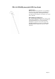
PDL-4 A.C.ID-M System (with GPS) User Guide SmartProbe-2 When pushed into the ground in close proximity to the target cable, and activated, the SmartProbe-2 receives the applied A.C.ID-M signal and relays A.C.ID-M status information to the PDL-4 via a shortwave radio link. Extended Range SmartProbe-2 The extended range SmartProbe-2 is used to locate cables that are buried too deep to be located by the standard SmartProbe-2.
PDL-4 A.C.ID-M System (with GPS) User Guide Global Positioning System (GPS) When the green button on the VectorBar or SmartProbe 2 is pushed the GPS system will automatically calculate the position of the receiver. PDL-4 Receiver Features On/Off Key Press and hold for one second to switch the PDL-4 receiver On or Off. Display Contrast. With the PDL-4 switched off, press and hold the On/Off key. After a few seconds, the contrast will automatically cycle through its range.
PDL-4 A.C.ID-M System (with GPS) User Guide In Direct Selection mode, and when using other screens requiring selection from a list, rotate the Gain Control to move the highlight bar up or down. Rotate the gain control to adjust the contrast when the Contrast screen is displayed. Speaker Sounds The volume is controllable in four steps: Off, Low, Medium and High, via the menu system. PDL-4 The speaker sounds are as follows: 1.
PDL-4 A.C.ID-M System (with GPS) User Guide Conditions resulting in the Alert tone include: a) b) The battery becoming almost exhausted The Inactivity Timer expiring. When the volume is set to Off, the speaker will still generate key press confirmation "beeps" and the "Error" tone - but at the lowest audible level. When the unit is first switched on, it will select the volume setting last used.
PDL-4 A.C.ID-M System (with GPS) User Guide To replace batteries proceed as follows: • • • • Release battery-housing cover by means of the release catch, situated under the carrying handle Remove battery or batteries Insert new battery or batteries, ensuring correct installation, as indicated on the label within the battery housing Close battery-housing cover. VectorBar and Extended Range VectorBar When activated the VectorBar, or extended range VectorBar, transmits its battery status to the PDL-4.
PDL-4 A.C.ID-M System (with GPS) User Guide To replace the batteries proceed as follows: • Unscrew the quick-release screws a quarter of a turn, anti-clockwise • Remove batteries • Insert new batteries, ensuring that they are installed correctly, as indicated on the diagram within the battery housing • Replace covers • Screw in quick-release screws a quarter of a turn clockwise. One battery compartment at also houses an RS232 socket for software download.
PDL-4 A.C.ID-M System (with GPS) User Guide Enabling GPS GPS can be manually enabled or disabled. To change the setting proceed as follows: § § § § § § Switch the locator On Press the Exit Key Press System Menu Press User Preferences Press GPS Power Options key Select option When the locator is switched off, it will remember the last GPS mode it was in.
PDL-4 A.C.ID-M System (with GPS) User Guide On the screen, "SV's 5" (Solar Vehicles) refers to the number of satellites used to calculate the position during a Cold Start. This number will be 5 or more, depending on the number of satellites providing cover at the time of the fix. Display Fix Selecting Display Fix will give a read-out of the current GPS position of the locator. Performing a Display Fix is similar to the procedure for a Cold Start.
PDL-4 A.C.ID-M System (with GPS) User Guide • Backlight Off, On, Auto. Clock -Daylight Saving, Time Zone, Time Format, Time, Date. § Upload, Download, Defaults, Test Upload Data Log Start, Cancel. Download S/W Upgrade Start, Cancel. • Restore System Defaults Confirm Restore, Cancel. • Self-Test – Automated tests and results followed by further manual test options.
PDL-4 A.C.ID-M System (with GPS) User Guide options: • VectorBar VectorBar screen prompts for the green button to be pressed. • SmartProbe SmartProbe screen prompts for the green button to be pressed. § A.C.ID Clamp • Non A.C.ID Confirmation Pot Hole, Confirmation Other options. Cable Locate Pressing the cable locate menu key takes the PDL-4 into the cable locate screen. § Feature Configuration- This feature is for Radiodetection use only.
PDL-4 A.C.ID-M System (with GPS) User Guide Direct Selection Direct Selection allows quick selection of any menu item from a list, without having to use the menu structure. Press and hold the Exit key for one second to display the Direct Selection screen. Select the function required by rotating the Gain Control to move the highlight bar down (clockwise) or up (anti-clockwise) then access that function by pressing the Select key.
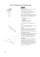
PDL-4 A.C.ID-M System (with GPS) User Guide To deploy the arm, release the catch on the carrying handle and lift the arm at the green button end of the VectorBar 20. Continue lifting the arm until it is fully extended and locks into the fully deployed position. When the arm is fully deployed, the green LED next to the swivel mechanism will illuminate. To stow the arm lift it at the free end until it swings back into the fully stowed position. Engage the catch in the carrying handle.
PDL-4 A.C.ID-M System (with GPS) User Guide Tracing Procedure Tracing the cable between confirmation locations is carried out using both Peak and Null modes. Peak mode is preferred as, in null mode, the signal is easily distorted. Peak Rotate the PDL-4 until the orientation line in the centre of the Cable Orientation Indicator is aligned with the North/South marks.
PDL-4 A.C.ID-M System (with GPS) User Guide Select 'Perform CD Reset' and when prompted confirm that a CD Reset is required. 'CD Reset Successful' is displayed when the CD Reset is successfully completed. The CD arrow will point away from the transmitter (towards end ground) when the PDL-4 is over the target cable.
PDL-4 A.C.ID-M System (with GPS) User Guide Note: Do not move or touch the VectorBar while it is calculating. The VectorBar can be deactivated by pressing and holding the green button, until the LED extinguishes. When the green button is pressed on the VectorBar the PDL-4 will automatically switch to VectorBar mode and display the following information: VectorBar software version. VectorBar battery condition. Tilt angle of bar. 'Waiting for Data'. 'Checking A.C.
PDL-4 A.C.ID-M System (with GPS) User Guide A.C.ID-M signal, and the VectorBar will continue looking. 0 If the VectorBar is tilted, but by less than 45 , the Intermediate Result screen is displayed. If the VectorBar has not been placed above the target cable the 'Reposition the VectorBar' screen will be displayed indicating the distance and direction that the VectorBar must be moved.
PDL-4 A.C.ID-M System (with GPS) User Guide If the EXIT button is pressed depth and current will be logged without GPS data. 0 If the VectorBar is tilted at an angle of more than 45 0 the 'Tilt angle too great (45 maximum)' screen is displayed. Successful confirmation cannot be achieved until the tilt 0 angle is reduced to less than 45 .
PDL-4 A.C.ID-M System (with GPS) User Guide The arrow on the top of the SmartProbe-2 must be pointing along the line of the cable, away from the LMS-3 transmitter (towards the end ground point). If the ground is hard, it may be necessary to start spade, potholer or MED. Press the SmartProbe-2 green button. For customers with more than one A.C.ID-M code the button should be pressed repeatedly until the required A.C.ID-M code is displayed.
PDL-4 A.C.ID-M System (with GPS) User Guide If the tip of the SmartProbe-2 is outside the Confirmation Zone, but not further than 4 ft from the target cable, the 'Reposition the SmartProbe-2' screen is displayed at one of two zoom levels (maximum horizontal displacements of 2 ft or 4 ft). 'Position Estimate' is displayed across the screen. If the probe tip is close to or within the Confirmation Zone, and the A.C.
PDL-4 A.C.ID-M System (with GPS) User Guide Depth Warning Raise and lower the handle forcefully to penetrate the ground until the Disc reaches ground level. Note: If the Disc jumps off the Outer Sleeve this indicates that penetration has exceeded the desired depth. Further Penetration Should further penetration be required, remove the Outer Sleeve and Disc, reposition the Collets/'O' ring to the desired depth groove, then carry out the Depth Indicator assembly procedure previously described. Non A.C.
PDL-4 A.C.ID-M System (with GPS) User Guide Note: Before connecting the PDL-4 to a PC or Laptop PC the following precautions must be taken. • To reduce the effect of static electricity, wipe the PDL-4 with a damp cloth. • Wear an earthed wrist strap. Upload Data Log The Upload Data Log option allows the contents of the PDL-4 Data Log, including GPS information, to be uploaded to a PC or LMS-3.
PDL-4 A.C.ID-M System (with GPS) User Guide Download Software Upgrade The Download Software Upgrade option allows new PDL-4 software to be downloaded from a PC or LMS-3. Connect the PDL-4 to the PC using an RS232 cable. Press the Cancel menu key or the Exit key to return to the System Utilities menu screen (without performing a download). Press the Start menu key to initiate data transfer.
PDL-4 A.C.ID-M System (with GPS) User Guide Press the Cancel menu key or the Exit key to return to the System Utilities menu screen (without restoring defaults). After the defaults are restored 'System defaults restored' is displayed for five seconds (unless any key is pressed or the gain control is operated) and the receiver enters the operating mode last used. Self-Test To initiate a Self-Test, press and hold the On/Off key for four seconds or select it from the System Utilities menu.
PDL-4 A.C.ID-M System (with GPS) User Guide GPS User Guidelines Buildings, foliage, and people can block signals from GPS positioning satellites. The ideal location using GPS is a wide-open space, with an unobstructed view of the sky in all directions. Make sure the unit has an unobstructed view of the sky before trying to obtain a fix. Trying to obtain GPS readings in poor coverage areas may result in longer fix times and reduced PDL-4 battery life.
PDL-4 A.C.
PDL-4 A.C.ID-M System (with GPS) User Guide VectorBar 20 Technical Specification Description: VB20 VectorBar. Part No: 10/AA2614. Physical: Construction Aluminium Extrusion weatherproof to IP54. Extending arm to improve depth performance. Ruggedness Withstands 0.6 metre (2 ft) drops onto concrete (BS EN 60068-2). Dimensions (with arm stowed) (with arm deployed) 19(H) x 186(W) x 19(D) cm. 7.5(H) x 73(W) x 7.5(D) in. 27(H) X 292(W) X 19(D) cm. 10.5(H) X 115(W) X 7.5(D) in.
PDL-4 A.C.ID-M System (with GPS) User Guide Operating Temperature Range:− − 20 °C to +50 °C (− − 4 °F to +122 °F). Environmental Protection: Shock BS EN 60068-2-29. Vibration BS EN 60068-2-6. Freefall Dust and Water Resistance BS EN 60068-2-32. BS EN 60529 (IP 54). Miscellaneous: Options Tilt Sensor. Compatibility Radiodetection PDL-4 Locator, Handheld Data Viewer. Quality Control BS5750/ISO 9001/EN29001. Compliance Warranty Part 15 FCC. 12 months.