Radio Systems Millenium-A Console Page 1 Radio Systems Millenium-A Analog Console Installation and Operation Manual Radio Systems Millenium Analog Broadcast Manual — Part # MAN-MILLCONA For Console Models: RS-6A RS-12A RS-18A RS-24A Manual Revision 08-06-2014 for serial numbers 101255 and higher Revised to include Illustration B-1 Updated to detail new Control Board part #18516 Illustration B-1 Updated to detail “classic” remote control protocol Sect 2.2.
Radio Systems Millenium-A Console Installation/Wiring/Operation............................................................6 1.1 1.2 1.3 1.3.1 1.3.2 1.4 1.4.1 1.4.2 1.4.3 1.4.4 1.4.5 1.4.6 1.5 1.5.1 1.5.2 1.5.3 1.5.4 1.5.5 1.5.6 1.5.7 1.5.8 1.5.9 1.5.10 Illus. A-1 Illus. A-2 Console Placement................................................................... 6 Opening the Console................................................................ 6 Power Supply................................................
Radio Systems Millenium-A Console Illus. B-2 Illus. B-3 Illus. B-4 Remote Control Wiring (factory default with cue for IFB)....... 17 Remote Control Wiring (“classic” mode)................................. 18 Monitor Board Wiring.............................................................. 19 Six Channel Audio Board................................................................20 3.1 3.1.1 3.1.2 3.1.3 3.2 3.2.1 3.2.2 3.3 3.3.1 3.3.2 Illus. C-1 Illus. C-2 Illus. C-3 Input Connectors...................
Radio Systems Millenium-A Console Illus. E-3 Illus. E-4 Illus. E-5 Illus. E-6 Illus. E-7 5.2 5.2.1 5.2.2 5.2.2.1 5.2.2.2 5.2.2.3 5.2.2.4 5.2.2.5 5.2.3 Four Source Router Card....................................................... 36 DA-Mixer Card........................................................................ 37 DA-Mixer Programming Examples......................................... 38 Intercom Card Wiring..............................................................
Radio Systems Millenium-A Console Illustration Illustration Illustration List Illustration Illustration List Illustration Illustration List Illustration Illustration Illustration List Illustration Illustration List Monitor Board Schematic..................................................... D-6 Monitor Board Parts Layout Top........................................... D-7 Monitor Board Parts Layout Bottom...................................... D-8 Monitor Board Parts List....................................
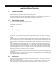
Radio Systems Millenium-A Console Page 6 Installation/Wiring/Operation 1.1 Console Placement Because neither ventilation, or rear access is required, the console may be mounted on any sturdy surface. Opening the lid provides access to all electronics, internal controls and wiring points. After placing the console, open the lid and mark the cable access slots on the chassis bottom on the table surface. Remove the console and cut the slots with a saber saw.
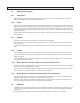
Radio Systems Millenium-A Console 1.4 Wiring Access Layout 1.4.1 Connectors Page 7 Millenium Analog Consoles can be ordered with RJ-45 female connectors, pinned out to the StudioHub+ standard, or with 5-pin removable barrier strip connectors (quick connector). 1.4.2 Inputs All audio inputs and audio patch points wire to the Six Channel Audio Board(s) on the base of the console. One board is utilized for every 6 channel positions. Audio inputs are stereo and balanced.
Radio Systems Millenium-A Console 1.5.1 Page 8 Input Assignment Traditionally, commonly used inputs are assigned to input “A”. This gives the operator quick assurance of proper input selection. 1.5.2 Mic Use Mic channels should always be activated with the slider down, and then potted up to avoid a sudden “room rush” of background sound. Cue speaker muting is only provided when a mixing channel is turned “on”.
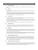
Radio Systems Millenium-A Console 1.5.8 Page 9 VU Meter Selection (6 Channel Consoles Only) The six channel console provides only three meters. One meter is dedicated to the TEL output, while the remaining two are selected by a front panel switch to display either PGM or AUD outputs. The peak LEDs in the meters also follow the VU meter select switch. 1.5.9 Remote Control The Millenium Consoles provide extensive remote control using a 15-pin D connector located at each mixing channel.
Radio Systems Millenium-A Console Page 10 Illustration A-1 CT-2002 Console Clock/Timer
Radio Systems Millenium-A Console Illustration A-2 CT-2002 Console Clock/Timer Wiring Diagram Page 11
Radio Systems Millenium-A Console Page 12 Six Channel Control Board 2.1 Overview One Six Channel Control Board is provided for every six input channels. This card sends DC control voltages to the Six Channel Audio Board that: Select A/B Inputs Set output bus and cue routing Set input level attenuation Activate muting buses Activate timer reset bus This information is conveyed by a 16 conductor ribbon cables; one cable for every mixing channel.
Radio Systems Millenium-A Console 2.2.2 Page 13 Remote Control Options – by Channel Fader Start – The channel may be programmed to automatically turn on whenever the fader is brought out of the detent (cue) position. All programmed channel on functions (e.g. remote starts or timer reset) will activate at this time. Note that a special order fader with detent (RS Part # P&G) is required for this option. Insert jumper A to activate. Default is no jumper; no fader start 2.2.
Radio Systems Millenium-A Console 2.2.5 Page 14 Timer Reset The insertion of timer reset jumpers programs operation of the timer reset bus in conjunction with a selected input. The bus will go low momentarily (100 ms) when the mixing channel is first placed into the “On” mode. Depressing the “On” button after the channel is already turned “On”, will result in another pulse of the bus. Insert jumper S for input A to reset the timer. Default is no jumper; no timer reset.
Radio Systems Millenium-A Console 2.2.8 Page 15 Off (Ready) Lamp Options These jumpers allow for local (console) or remote (source) control of the channel off (ready) lamp via the remote control connector. Install jumper X between the left and middle header pins for input A local Off lamp control. Install jumper X between the middle and right header pins for input A remote Off lamp control. Default is left and middle pins jumpered; local off lamp control.
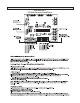
Radio Systems Millenium-A Console Page 16 Illustration B-1 Six Channel Control Board Jumper Settings for Millenium Analog Consoles Part # 18516 A B C D E F H J K L M N AA P R S T U V 1 2 1 2 1 2 W 1 2 X Y Z Board Channel Logic Jumpers Location* A Install for fader start (special order fader required) B Install for remote B start and stop commands to control the remote outputs C Install for input B to hold and remove for input B to pulse the remote pulse/hold outputs D Install for remote A
Radio Systems Millenium-A Console Page 17 Illustration B-2 Remote Control Wiring - with remote cue available for IFB (for console models shipped after 10/15/10 with control prom PN: 18406) Note: Jumper E on Input Control Board must be removed to initiate this mode of remote control (this is factory default setting) Remote Control On/Off Inputs to the Console Channel (with input A or B selected) (with input A or B selected) Cue On Control Memory Recall Control ** Remote Control Start/Stop Outputs from
Radio Systems Millenium-A Console Page 18 Illustration B-3 Remote Control Wiring - “Classic” Version (for console models shipped after 10/15/10 with control prom PN: 18406) Note: Jumper JU213 on Input Control Board must be installed to initiate this mode of remote control.
Radio Systems Millenium-A Console Page 19 Illustration B-4 Monitor Board Wiring Console Side In-Console Resistor Socket (for 15V operation) LED 4 Selector Connector (1 of 2) Right connector for switches & LEDs 1-4 Left connector for Switches & LEDs 5-8 Remote Wiring Side LED 3 1 LED 2 2 3 LED 1 4 5 Switch Common 6 Switch 1 7 Switch 2 8 9 LED 4 Control 10 LED 3 Control 11 LED 2 Control 12 LED 1 Control 13 14 15 Use console internal 15 Volt power supply or any external 5 to 15 Volt su
Radio Systems Millenium-A Console Page 20 Six Channel Audio Board 3.1 Input Connectors Illustration C-1 shows the location of all board input and patch point connectors as well as the pin-outs of the connectors for 5-pin version consoles. Illustration C-2 shows the location of all board input and patch point connectors as well as the pin-outs of the connectors for RJ-45 version consoles. 3.1.1 Input Wiring Every input, from mic thru high level wires to the input connectors.
Radio Systems Millenium-A Console Page 21 nel input. The only exception is that a special IAD (factory provided as part # “AT-M”) is utilized to increase the input sensitivity any time a mic is used. Five standard IAD’s are provided by the factory. These include the one for use with mics, and four standard values of input attenuation. Illustration C-3 charts which IAD should be utilized under different source level combination situations, and shows the parts values any construction of the IAD’s. 3.
Radio Systems Millenium-A Console Page 22 Illustration C-1 Six Channel Audio Board - 5 Pin Jumper Programming SIX CHANNEL INPUT BOARD with 5 Pin CONNECTORS 1 IN CH Input or Chassis Ground Select IN CH IN CH IN CH IN CH IN CH IN CH IN CH IN CH IN CH IN CH INPUT 6A INPUT 6B INPUT 5A INPUT 5B INPUT 4A INPUT 4B INPUT 3A INPUT 3B INPUT 2A INPUT 2B INPUT 1A INPUT 1B 2 Input Ground IN CH 3 Chassis Ground (Default) 5 4 Mono/Stereo Select Stereo Input (Default) CBA CBA CBA CBA CBA
Radio Systems Millenium-A Console Page 23 Illustration C-2 Six Channel Audio Board - RJ-45 SIX CHANNEL INPUT BOARD with RJ-45 CONNECTORS Jumper Programming 1 IN CH Input or Chassis Ground Select INPUT 1B 2 Input Ground IN CH IN CH IN CH IN CH IN CH IN CH IN CH IN CH IN CH IN CH IN CH INPUT 1A INPUT 2B INPUT 2A INPUT 3B INPUT 3A INPUT 4B INPUT 4A INPUT 5B INPUT 5A INPUT 6B INPUT 6 A 3 Chassis Ground (Default) 5 4 Mono/Stereo Select Stereo Input (Default) CBA CBA CBA CBA C
Radio Systems Millenium-A Console Illustration C-3 Input Attenuator (IAD) Programming + Page 24
Radio Systems Millenium-A Console Page 25 Output Board 4.1 Overview This circuit board provides the following console functions: Line output amplification Cue amplification Headphone amplification External Inputs Monitor sends Meter and peak LED functions Level sets for all functions Muting and timer reset functions Power supply interface Talk back circuitry Illustration O-1 provides a complete layout of all connectors, level set locations, and all user connector pin-outs for the 5-pin version console.
Radio Systems Millenium-A Console Page 26 These inputs are intended mainly for air signal monitors, or for the connecting of other external monitor sources. Input level trims for each of these inputs are provided on the Output Board. 4.2.4 Headphone Outputs Two headphone outputs are provided. The first is available at a stereo, quarter inch, phone jack which is factory mounted to the front panel. This output is capable of driving 8 ohm or greater loads. D0 NOT USE MONO HEADPHONES.
Radio Systems Millenium-A Console 4.4 Page 27 Talk Back Connections The talk back circuit has two sections, send and receive. The send section will output any signal applied to its input when the front panel Talk Back Switch is depressed. Return signals are applied to Cue Bus for operator monitoring. A trim pot on the Output Board is provided to set the external cue input level.
Radio Systems Millenium-A Console Page 28 4. Move the voltmeter, and adjust the right program output, followed by the left audition output, right audition output and mono output. 4.5.2 VU Meter “0” Calibration The console was calibrated at the factory for an output level of +4dBv, into 600 ohms, when the VU meters indicate “0”. To calibrate the VU meter “0” indication: 1. Perform output level calibration as detailed previously. 2.
Radio Systems Millenium-A Console Page 29 Illustration O-1 Output and Meter Board - 5 Pin TEL J33 AUD OUT EXT IN3 EXT IN1 J29 J25 MON MUTE2 PHONES J19 J15 J11 J16 J12 EXT IN4 EXT IN2 UNMUTED MON MON MUTE1 PGM OUT J7 TALKBACK OUT J30 J36 J26 J20 IN-4 IN-3 IN-2 IN-1 14 11 TALKBACK IN/CUE J37 TALKBACK OUT 7 RIGHT 9 U25 U24 U14 U9 15 12 10 8 LEFT U29 26 IN-4 IN-3 IN-2 IN-1 EXT INPUT LEVEL RIGHT TO MONITOR SELECT BOARD VR1 U1 U30 U10 METER CAL PGM LEFT 27 U31 METER CAL PGM RIG
Radio Systems Millenium-A Console Page 30 Illustration O-2 Output and Meter Board - RJ-45 TEL AUD OUT J33 J29 J25 J19 J15 J11 J30 J26 J20 J16 J12 TALKBACK OUT J36 EXT IN3 EXT IN1 EXT IN4 EXT IN2 UNMUTED MON MON MUTE1 PGM OUT IN-4 IN-3 IN-2 IN-1 9 14 11 TALKBACK IN/CUE J37 TALKBACK OUT 7 RIGHT U25 U24 U14 U9 15 12 10 8 LEFT U29 26 MON MUTE2 PHONES IN-4 IN-3 IN-2 IN-1 U30 METER CAL PGM LEFT 27 U31 METER CAL PGM RIGHT 28 U32 METER CAL AUD LEFT 29 U33 METER CAL AUD RIGHT
Radio Systems Millenium-A Console Page 31 Illustration O-3 Auxiliary Control Relay Wiring Connect the auxiliary relay (optional) (RS part #7699) to the console muting connector as shown below for mute-1 or mute-2 control of air lights and other outboard equipment. A solid-state model of this relay (RS part #9375) is also available. Note that this part is only supplied in single pole (SPST) configuration.
Radio Systems Millenium-A Console Page 32 Illustration O-4 Talkback Wiring
Radio Systems Millenium-A Console Page 33 Interface Options and Accessories 5.1 Overview Several optional interface cards are available for the Millenium-A consoles. These options include: Enhanced Remote Interface Card - This card connects any input channel’s 15-pin remote connector to provide relay and opto-isolated channel on/off and start/stop control. Selector Logic Card - This card adds control logic to the 8 switches located to the right of the monitor section.
Radio Systems Millenium-A Console Page 34 Illustration E-1 Enhanced Remote Interface Card Description This option card connects to any input channels’ 15-pin remote connector to provide relay and opto isolated channel on/off and start/stop control. Jumpers are also provided to program various enhanced logic states.
Radio Systems Millenium-A Console Page 35 Illustration E-2 Selector Logic Card
Radio Systems Millenium-A Console Page 36 Illustration E-3 Four Source Router Card
Radio Systems Millenium-A Console Page 37 Illustration E-4 DA-Mixer Card Description This optional, compact circuit card installs internally in Millenium consoles and may be connected to any console audio output(s) to distribute signal to multiple sources. The card features bridging inputs, low impedance outputs, and independent level adjusts for each output. Installation Use the plastic pins supplied to mount the circuit card on any free slot on the console inside rear wall.
Radio Systems Millenium-A Console Page 38 Illustration E-5 DA-Mixer Programming Examples Various Output Configurations and Applications for the Radio Systems DAMIXER Console Option Card 1 2 3 4 Output Programming Jumpers JU1-JU8 (black over pin 1 indicates user installed jumper) 1 2 3 4 1 2 3 4 1 Out B Out A 2 3 4 1 Out C 2 3 4 1 Out D 2 3 4 1 Out E 2 3 4 1 Out F 2 3 4 1 Out G 2 3 4 Out H Stereo DA - 1x4 Single stereo input (1/2) to 4 stereo outputs (A/B, C/D,
Radio Systems Millenium-A Console Page 39 Illustration E-6 Intercom Card Wiring To interconnect the Intercom Card to Radio Systems' Millenium Analog Consoles Output Board Talk-Back Connectors Table-top/Console Programming (Program J1 thru J4) Jump left pins for table-top Jump right pins for console Intercom Audio These pre-made factory cables included with the squawk box card (To J36 & J37 on the output bd.
Radio Systems Millenium-A Console Page 40 Illustration E-7 Intercom Card Table-Top Speaker & Console Interconnection Intercom Card (Internal to Console) Table-top/Console Programming (Program J1 thru J4) Jump left pins for table-top Table Top Speaker Drive Volume Jump right pins for console Remote Console Drive Volume Table Top Speaker Receive Volume Remote Console Receive Volume Console Intercom 1 + Console Intercom 1 - 1 2 Shield Table Top Speaker 1 Hot 3 4 Table Top Speaker 1 Switched Console
Radio Systems Millenium-A Console 5.2 Page 41 Intercom Card Overview The Intercom is an optional accessory for the Millenium broadcast consoles. The card provides 2-way amplification for connection of the console to any combination of four speakers or Radio Systems’ consoles. One or two cards may be installed in a console to service four or eight stations. 5.2.1 Operation 1.
Radio Systems Millenium-A Console 5.2.3 Page 42 Calibration Adjust the output level control on the intercom card for more level at the remote speakers or console. Adjust the external cue level control on the analog output board to set the intercom input level and to balance it with the cue level of the internal console cue inputs.
Radio Systems Millenium-A Console Page 43 Maintenance and Troubleshooting 6.1 Overview There is no required maintenance for Millenium consoles. Front panel level controls and switches will not become noisy since they control only DC for the VCAs and CMOS analog switches. A very dirty fader control will skip levels erratically. Normal cleaning agents may be used to clean the controls. Painted surfaces should be cleaned with a warm damp cloth with mild detergent.
Radio Systems Millenium-A Console Page 44 connection at header J9, a defective U9 and/or U10, or a defective R91, R93, R99, R100, R101, R102, R103, or D3, will cause this problem. If this problem is occurring in only one channel, suspect U10 (left channel) or U9 (right channel). 6.4 Six Channel Control Board Read the Theory of Operation before troubleshooting. The Six Input Control Board utilizes a microprocessor and clue logic. Each section is identical and isolated from all others.
Radio Systems Millenium-A Console Page 45 2c. Connect a distortion analyzer to the defective output and adjust the associated VCA distortion null for a minimum distortion reading on the analyzer. 3a. For a defective cue VCA, set the fader to “cue.” 3b. Set the cue headphone level control to 1/2 full. 3c. Connect a distortion analyzer to the cue speaker and adjust the associated VCA distortion null for a minimum distortion reading on the analyzer.
Radio Systems Millenium-A Console Page 46 Theory of Operation 7.1 Power Supply Circuit Description The external power supply provided with Millenium Consoles contain internal modules which provide +15v and -15v at 6 Amps. Each supply is internally fused. Output voltages from the modules are connected to the Power Supply Interface Board at J1 and J4. The internal modules are further regulated to provide +7.5 and -7.5 volts required by the console.
Radio Systems Millenium-A Console RB3 High when the Audition Bus is selected RB4 High when the Telephone Bus is selected RB5 High when the Cue Bus is selected RB6 High when the channel is on RB7 High when the channel is off Page 47 RE0 High (momentary or maintained) to provide a remote control pulse or holding signal when the channel is turned on.
Radio Systems Millenium-A Console Page 48 The VCA is a current in, current out device, which may provide amplification as well as attenuation of the signal from U3C. The VCA is capable of over 100 dB of level control, depending upon the control voltage applied to pin 3 of the VCA. The front panel linear taper fader supplies a control voltage ranging from +7.5v at the minimum setting of the fader to 0 volts at the maximum setting.
Radio Systems Millenium-A Console Page 49 U3 sets the state of its output ports depending on the signals (switches) present at its input ports (RC and RD). U2 and U4 converts the output of U2 to the BCD format required by the analog switches on the Output Board. Transistors Q1, 2, 3, 4, 6 and 7 provide an interface between the logic level signals and those required by the Output Board. Transistors Q5 and Q8 interface the Timer Auto Reset and Start signal with the Clock/Timer.
Radio Systems Millenium-A Console Page 50 connected to the input of U20. Each external input has an associated trimmer for level adjustment. The voltage at U20 pins 6, 9, 10, 11 are generated on the Monitor Control Board.
Radio Systems Millenium-A Console Page 51 2. Change the grounding system. The console routes all signal and control grounds to a single ground point at the powersupply. This is usually the preferred method to minimize noise and RFI. However, on the input(s) or output(s) you have determined to be causing RF interference, you should reroute the ground. If the interference persists, reroute the input or output ground wire to the console chassis ground.
TITLE: SIX CHANNEL CONTROL BOARD D-2 Logan Township, NJ TYPE: MILLENIUM RS-A CONSOLE DATE: PARTS LAYOUT-TOP SIDE 7-29-2008 PART NO: 18516 REV: E
TITLE: INPUT CONTROL BOARD D-3 Logan Township, NJ TYPE: MILLENIUM RS-A CONSOLE DATE: PARTS LAYOUT - BOTTOM SIDE 9-2011 PART NO: 18516 REV: E
SIX CHANNEL CONTROL BOARD PARTS LIST RS Part # Manufacturer Part # 18517 CD74HC08PW U1,3,9,10,14,15, 19,20,24,25,29,30 74HC08 TI QUAD 2-INPUT POS-AND GATE 12 18518 SN74HC157PW U4,8,13,18,23,28 74HC157 TI QUAD 2-TO-1-LINE DATA SELECTOR/MULTIPLEXER 6 16005 ECJ-2YB1H104 K SURFACE MOUNT CAPACITOR 0.048 X 0.079 INCHES 36 15505 ICF-314-T-O 16655 Reference Description Manufacturer Descrip. Qty .
SIX CHANNEL CONTROL BOARD PARTS LIST RS Part # Manufacturer Part # 16575 RC0805FR-071OKL 16019 17022 RC0805FR-071 KL 16023 ERJ-6ENF2211 RC0805FR-073 57RL 14667 RC0805FR-074 K7L 16041 RC0805FR-074 22RL 16916 14468 RC0805FR-074 7K5L ERJ-6GEYR00 16025 ZXMN6A07FTA Reference Description R1,R3-9,14,15,17,23,27-32,34-39, 41,42,44,51,54,74,79-104,108,557, 56,64,69,72,73,78,128,133-158,162, 110,111
D-6
S4 S3 D3 D2 S14 S11 D10 D7 S1 S2 D1 S5 S15 S12 D11 D8 S16 S13 D12 D9 S8 D4 S9 D5 S6 S7 S10 D6 S24 S21 S20 S17 D20 D17 D15 D13 S25 S22 S18 D21 D18 D14 S28 S23 S19 D22 D19 D15 S30 S29 S27 D25 D24 S28 D23 10886A TITLE: MONITOR BOARD D-7 Logan Township, NJ TYPE: MILLENIUM RS-A CONSOLE DATE: PARTS LAYOUT 7-29-2008 PART NO: 10887 REV: E
J10 J9 D26 C1 + C3 U1 + C4 R2 C5 R4 C2 + J1 D27 J2 Q5 U3 R1 Q1 Q2 D28 Q3 Q4 Q6 Q7 Q8 R2 J4 U2 Q9 U4 C6 C7 J3 C8 10886A D33 R22 R7 D31 D30 + D32 + R23 D34 R5 D29 R6 J5 R24 C9 J6 + R25 R26 R27 C10 J7 J8 TITLE: MONITOR BOARD D-8 Logan Township, NJ TYPE: MILLENIUM RS-A CONSOLE DATE: PARTS LAYOUT 7-29-2008 PART NO: 10887 REV: A
MONITOR BOARD PARTS LIST LINE PART # DESCRIPTION REFERENCE DESIGNATION QTY. 3 20 30 10886 7602 5744 1 25 5 40 5743 50 9124 60 8191 70 13051 80 7012 90 7786 100 1012 110 10928 120 5890 130 11157 140 5892 150 7050 160 10328 170 10326 180 5872 190 1143 200 7514 210 7533 220 1039 230 8228 240 3679 250 10891 260 11046 PCB MONITOR BD SHOULDER WASHER FOR TO‐220 CAP 100UF 25V RAD 20% Ref: C1;C2;C8;C9;C10 CAP .
7-29-2008 D-10
7-29-2008 D-11
D-12
CT-2002 CLOCK/TIMER PARTS LIST LINE PART # DESCRIPTION REFERENCE DESIGNATION QTY. 10 14400 CT-2002 CONSOLE C/T DETAIL 1 20 5729 RES 2.21K 1/4W 1% 16 Ref: R1;R2;R5;R6;R12;R11;R18;R17;R27;R26;R33;R32;R37;R36;R41;R40 30 2816 RES 10.0K 1/4W 1% 7 Ref: R22;R28;R24;R34;R14;R16;R19 40 1143 RES 100 OHM 1/4W 1% 50 1030 RES 470 OHM 1/4W 5% 7 Ref: R4;R7;R13;R35;R21;R38;R30; 5 Ref: R20;R23;R25;R29;R31 60 9806 RES 120 OHM 1/4W 5% 1 Ref: R39 70 3558 RES 5.
LINE PART # DESCRIPTION REFERENCE DESIGNATION QTY. 240 3679 VR 7805 1 260 14505 IC LTC1690 Ref: U2 1 Ref: U4 270 14359 PHOTODETECTOR 1 Ref: U1 280 1011 SOCKET 8 PIN DIP 290 8228 SOCKET 40 PIN IC 300 11338 RJ45 VERTICAL SHIELDED 1 Ref: REF;U4 1 Ref: REF; U3 2 Ref: J5;J6 310 14504 CONNECTOR 9 PIN D FEMALE 1 Ref: J7 320 7050 HEADER 2 PIN MTA .1 330 5892 HEADER 3 PIN MTA .1 340 7051 HEADER 4 PIN MTA .1 1 Ref: J2 1 Ref: J4 1 Ref: J1 350 5890 HEADER 7 PIN MTA .
LINE PART # DESCRIPTION REFERENCE DESIGNATION QTY. 500 9320 SCREW PHIL PH 4-40 X 5/16 1 510 1014 CAP 10UF 25V NP Ref: REF; U2 2 Ref: C14;C15 520 7792 RES 1.
7-29-2008 D-16
7-29-2008 D-17
7-29-2008 D-18
7-29-2008 D-19
7-29-2008 D-20
7-29-2008 D-21
SIX CHANNEL AUDIO BOARD - RJ-45 VERSION 7-29-2008 Blank Board 16794 Assembly 16796 D-22
SIX CHANNEL CONTROL BOARD PARTS LIST LINE PART # 10 20 16794 10731 30 16907 40 10726 50 10726 60 16021 70 16908 80 16909 90 16910 100 14424 110 16074 120 16911 130 16912 140 16913 150 16149 160 16914 170 16915 180 16399 185 16562 190 14467 200 16916 210 16351 220 16917 230 16918 240 16511 DESCRIPTION REFERENCE DESIGNATION PCB SMT SIX CHANNEL AUDIO BD RES SMT 1.0M 1/10W 1% Ref: R73-R120 RES SMT 1.
250 16919 260 16005 270 16901 280 16370 290 16346 300 1049 310 16902 320 16643 330 16903 340 16512 350 5751 360 16906 370 16900 380 16848 390 15340 400 16905 410 16063 420 16016 430 15505 440 16655 450 14841 460 5756 470 5755 480 16059 490 16904 500 5892 510 5749 520 11338 POT SMT TRIM 50K Ref: VR1-VR12 CAP SMT .
D-25
D-26
D-27
POWER SUPPLY INTERFACE PARTS LIST LINE PART # DESCRIPTION REFERENCE DESIGNATION QTY.
D-29
D-30
D-31
D-32
Analog Output Board Parts List LINE PART # 10 20 14799 2828 30 1009 40 8883 50 5876 60 10813 70 10813 80 5716 90 5723 100 5873 110 5726 120 8794 130 2816 140 2816 150 5872 160 8813 170 1143 180 9299 190 5882 200 5729 210 14810 220 5727 230 240 5734 5725 250 7512 DESCRIPTION REFERENCE DESIGNATION MILLENIUM OUTPUT BOARD DETAIL RES 4.7 OHM 1/2W 5% Ref: R19 RES 47 OHM 1/2W 5% Ref: R46;R47 RES 1.
LINE PART # 260 7513 270 10383 280 7482 290 5739 300 5743 310 5863 320 5860 330 5744 340 7012 350 1012 360 7535 370 15339 380 5865 390 14824 400 5751 410 6118 420 14850 430 6119 440 7995 450 1014 460 15340 470 1049 480 1011 490 1011 500 1039 510 13049 520 1027 DESCRIPTION REFERENCE DESIGNATION RES 49.
LINE PART # 530 1010 540 3675 550 1042 560 6120 570 5752 580 5756 590 5753 600 11338 610 7050 620 5892 630 7051 640 5890 650 5891 660 5749 670 7502 680 5893 690 7872 700 13047 710 7646 720 9142 730 14892 740 7518 750 9048 760 9662 DESCRIPTION REFERENCE DESIGNATION IC 5532 Ref: U9;U14-U18;U20-U25;U29-U43 IC 4558 Ref: U6 IC LM339N Ref: U26;U27;U28 IC 4051 Ref: U10;U11;U12;U13 IC 4053 Ref: U19 HEADER 26 PIN DUAL ROW .
Radio Systems Millenium-A Console Page 52 Millenium Console Specifications Models Available RS-6A: 6 Channel RS-12A: 12 Channel RS-18A: 18 Channel RS-24A: 24 Channel Audio Inputs Type: Differentially balanced instrumentation amplifiers with gain set jumpers and selectable input attenuators Level: Jumper selectable gain settings to accommodate nominal input levels from -60 dBm to +10 dBm.
Radio Systems Millenium-A Console Page 53 Millenium Consoles - Warranty and Repair Policies Warranty Radio Systems, Inc., warrants this equipment to be free from defects in materials and workmanship for a period of two (2) years for all electronic parts and subassemblies and a period of one (1) year for all mechanical parts such as faders and meters.. This warranty extends to first users of the product and future owners who purchase the product within the warranty period.