Radio Systems Millenium-D Digital Console Page 1 Radio Systems Millenium-D Digital Console Installation and Operation Manual Radio Systems Millenium Digital Broadcast Manual Part # MAN-MILLCOND For Console Models: RS-6D RS-12D RS-18D RS-6DNET (include network manual supplement) RS-12DNET (include network manual supplement) RS-18DNET (include network manual supplement) Manual Revision 11-05-2014 for serial numbers 100859 and higher Revisions to include Sect 2.2.
Radio Systems Millenium-D Digital Console Page 2 Installation/Wiring/Operation.................................................................................................. 5 1.1 1.2 1.3 1.3.1 1.4 1.4.1 1.4.2 1.4.3 1.4.4 1.4.5 1.4.6 1.5 1.5.1 1.5.2 1.5.3 1.5.4 1.5.5 1.5.6 1.5.7 1.5.8 1.5.9 1.5.10 1.5.11 1.5.12 Illustration A-1 Illustration A-2 Illustration A-3 Console Placement.........................................................................................................
Radio Systems Millenium-D Digital Console 3.2.1 3.3 3.3.1 3.3.2 3.3.3 3.3.4 3.4 3.4.1 3.5 Illustration C-1 Illustration C-2 Illustration C-3 Illustration C-4 Output Boards 4.0 4.1 4.1.1 4.1.2 4.1.3 4.1.4 4.1.5 4.2 4.2.1 4.2.2 4.2.3 4.2.4 4.2.5 4.3 4.3.1 4.4 4.5 4.6 4.6.1 4.6.2 4.6.3 4.6.4 4.6.5 Illustration D-1 Illustration D-2 Illustration D-3 Illustration D-4 Illustration D-5 Illustration D-6 Illustration E-1 Illustration E-2 Illustration E-3 Illustration E-4 Illustration E-5 Illustration E-6 5.1 5.2 5.
Radio Systems Millenium-D Digital Console 5.3.2.3 5.4 Page 4 Console interconnection............................................................................................... 44 Calibration.................................................................................................................... 44 Using Active Balanced Circuitry........................................................................................... 45 Six Channel Control Board Schematic F-1..............................
Radio Systems Millenium-D Digital Console Page 5 Installation/Wiring/Operation 1.1 Console Placement Because neither ventilation nor rear access is required, the console may be mounted on any sturdy surface. Opening the lid provides access to all electronics, internal controls and wiring points. After placing the console, open the lid and mark the cable access slots on the chassis bottom on the table surface. Remove the console and cut the slots with a saber saw.
Radio Systems Millenium-D Digital Console 1.4.3 Page 6 Control The front panel mounted Six Channel Control Board houses one 15 pin D connector to wire each channel’s remote control. Consult the Six Channel Control Board Section of this manual for detailed information on control remote functions and programming options. Consult the Interface Options and Accessories Section of this manual for detailed information on the optional interface card applications, wiring and function.
Radio Systems Millenium-D Digital Console 1.5.2 Page 7 Mic Use Mic channels should always be activated with the slider down, and then “potted up” to avoid a sudden “room rush” of background sound. Cue speaker muting is only provided when a mixing channel is turned “on”. Therefore, feedback can occur between the cue speaker or the monitor speakers (if cue monitoring is selected) and a mic input if the mic channel is placed in cue.
Radio Systems Millenium-D Digital Console 1.5.8 Page 8 Headphone Amplifier Output Select The headphone input select switches on the right-hand side of the console allow monitoring of program, audition, tel, cue and four external stereo inputs which are common to the headphone and monitor circuitry. All headphone outputs follow these switches. Level adjustment and connection for the operator’s headphones are provided on the front panel.
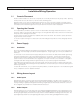
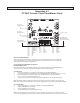
Radio Systems Millenium-D Digital Console Page 9 Illustration A-1 CT-2002 Console Clock/Timer/Master Clock To Console Output Board J1 To Console Monitor Board J3 Factory use only J5 Insert jumper for termination resistor (last slave clock in line) J6 Insert jumper for timer only operation J7 J7 (9 Pin D Female) J5 Serial Input (RJ-45) J6 Serial Loop-Thru (RJ-45) Pin 1 Pin 2 Pin 3 Pin 4 Pin 5 Pin 6 Pin 7 Pin 8 Pin 9 Pin 1 Pin 2 Pin 3 Pin 4 Pin 5 Pin 6 Pin 1 Pin 2 Pin 3 Pin 4 Pin 5 Pin 6 Seria
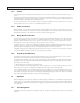
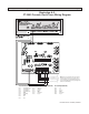
Radio Systems Millenium-D Digital Console Page 10 Illustration A-2 CT-2002 Console Clock/Timer Wiring Diagram + - J6 J5 Pin 6 Serial Data In - Pin 3 Serial Data In + Pin 1 Serial Data Out + Pin 2 Serial Data Out Pin 3 Serial Loop Out + Pin 6 Serial Loop Out - + Out to additional clocks (up to 32) J7 Note: Use pins 1&2 if this clock is the master (first) in the serial chain (a crossover cable is recommended).
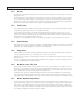
Radio Systems Millenium-D Digital Console Page 11 Illustration A-4 Illustration A-3 LED Meter Board with Talkback Microphone LED Meter Board with Talkback Microphone Radio Systems p/n 16636 Radio Systems p/n 16636 SELECT MIC Word Clock J2 MIX 2/7 MIX 1/6 UTL -9 -33 -13 MicPower -7 -5 -3 -1 +15v G -27 -25 -23 -21 -20 -19 -17 -15 -13 PROGRAM Meter Power 0 +1 +3 +5 +7 + 11 + -5 15 + 0 20 VU PPM VU dBFS -57 -37 -45 -25 -33 -13 JU1- Install for PPM / Remove for VU AUD 0 +1 +3
Radio Systems Millenium-D Digital Console Page 12 Six Channel Control Board 2.1 Overview One Six Channel Control Board is provided for every six input channels. This card sends DC control voltages to the Six Channel Audio Board that: Selects A/B Inputs Sets output bus and cue routing Sets input level attenuation Activates muting buses Activates timer reset bus This information is conveyed via 16 conductor ribbon cables; one cable for every mixing channel.
Radio Systems Millenium-D Digital Console 2.2.3 Remote Control Options – by Input 2.2.3.1 Pulse/Holding Remote Control Page 13 Insertion of these jumpers determine whether the remote control pins on the remote control connector pulse to ground when the channel is turned on, or remain at ground potential for the duration of the channel on state. Pulse mode is generally used for PC and CD player control. Holding mode is generally selected for skimmer and other units that require on/off control.
Radio Systems Millenium-D Digital Console 2.2.6 Cue Options by Channel 2.2.6.1 Cue on Fader Detent Page 14 Enable this function to allow the operator to put the channel in cue by dropping the fader into the detent (fully down) position. Note that a special-order fader with detent (RS Part #P&G) is required for this option. Insert jumper K to enable cue on detent Default is no jumper; no cue on detent 2.2.6.2 Auto Cue Cue follows channel On/Off mode with this option enabled.
Radio Systems Millenium-D Digital Console 2.2.9 Page 15 Analog/Digital programming Three-pin Jumper Z must be installed between the middle and upper pins in the Millenium Digital console, on every channel. This communicates channel on/off status to the console processor. 2.2.10 Remote Control Connector A 15-pin D connector is provided on the Six Channel Control Board for each channel to access all remote functions.
Radio Systems Millenium-D Digital Console Page 16 Illustration B-1 Six Channel Control Board Jumper Settings for Millenium Digital Consoles Part # 18522 Board Location* A B A B C D E F C D ER FQ H H J K L M N AA JQ KQ P R S T U V LQ MQ W Y 1 2 1 2 1 2 1 2 N P R S T U V W X X Z Y Z Channel Logic Jumpers Install for fader start (special order fader required) Install for remote B start and stop commands to control the remote outputs Install for input B to hold and remove for input B t
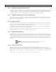
Radio Systems Millenium-D Digital Console Page 17 Illustration B-2 Remote Control Wiring - with remote cue available for IFB (for console models shipped after 10/15/10 with control prom PN: 18407) Note: Jumper E on Input Control Board must be removed to initiate this mode of remote control (this is factory default setting) Remote Control On/Off Inputs to the Console Channel (with input A or B selected) (with input A or B selected) Cue On Control Memory Recall Control ** Remote Control Start/Stop Outpu
Radio Systems Millenium-D Digital Console Page 18 Illustration B-3 Remote Control Wiring - “Classic” Version (for console models shipped after 10/15/10 with control prom PN: 18407) Note: Jumper JU213 on Input Control Board must be installed to initiate this mode of remote control Remote Control On/Off Inputs to the Console Channel Remote Control Start/Stop Outputs from the Console Channel Channel Stop Signal - Input A* Channel Stop Signal - Input B* Channel Start Signal - Input B* Channel Start Signal
Radio Systems Millenium-D Digital Console Page 19 Six Channel Audio Mother Board 3.1 Input Connectors The Millenium digital console may be ordered factory equipped with either 5-pin removable barrier strip connectors or RJ-45 style connectors. RJ-45 connectors are wired to the StudioHub+ audio standard. Both connectors accommodate either mono or stereo balanced or unbalanced analog connectivity or balanced AES-EBU or unbalanced S/PDIF connections.
Radio Systems Millenium-D Digital Console 3.3.4 Page 20 Phantom Power A mic may be supplied with Phantom power by installing jumper JU-12 on the Analog daughter plug-in card and a jumper on pins 4 & 5 on J-7 on the digital output card. Consult illustrations D3 or D4 for jumper locations. Note that the console provides +15 volts phantom mic power, which is suitable for most microphones. Consult the factory if a different (higher) phantom voltage is required. 3.
When an input is set for mic level it is automatically applied in MONO by summing the left input to both left and right output channels. Note: MIC LEVEL +15v and +48v phantom power is activated by inserting jumpers on J-7 on the digital output board.
Radio Systems Millenium-D Digital Console Illustration C-2 Digital Input Plug-In Board 15304 This board provies two AES/EBU or S-P/DIF digital inputs. On-board automatic sample rate conversion accommodates any source sample rate. This board can be plugged into any slot on the 6 input motherboard.
Illustration C-3 Description This board houses 6 channels of DIGITAL or analog input cards. Cards can be inserted in to any slot. This RJ-45 version of the board utilizes StudioHub+ standard pin outs for all analog and DIGITAL audio I/O. One of these boards per each 6 console channels mounts on the lower right of the console.
Illustration C-4 6 INPUT MOTHER BOARD 5 PIN CONNECTOR VERSION p/n 14904 Description This board houses 6 channels of DIGITAL or analog output cards. Cards can be inserted in any slot. This 5-pin connector version of the board utilizes 5-pin removeable barrier strip connectors for all analog and DIGITAL audio I/O. One of these boards per each 6 console channels mounts on the lower right of the console (See Manual Section 1.4.
Radio Systems Millenium-D Digital Console Page 25 Output Boards 4.0 Overview In the Millenium digital console two circuit boards provide all audio outputs and certain other related functions. The two large circuit boards are mounted on top of each other and are located on the right-hand inside pan of the console. The lower board provides most of the analog output functions and is identical to the circuit board utilized in Millenium analog consoles. The upper board provides mostly digital functions.
Radio Systems Millenium-D Digital Console 4.1.2 Page 26 “TEL” Output The “TEL” Output is connected via a five pin screw type barrier strip or RJ-45 connector labeled “TEL” on header J33, on the Output Board. The two “TEL” Outputs provided are in parallel, from the same amplifier. The combined load on the amplifier from both mono sends should be no less than 600 ohms. In other aspects, the performance and connections to the “TEL” Output are identical to the program and audition outputs. 4.1.
Radio Systems Millenium-D Digital Console Page 27 The Muted Output is intended to feed any other room which that contains microphones connected to the console. If it is desirable to feed all studios from a common amplifier, this amplifier should be fed from the Unmuted Monitor Output. External relays driven by the muting contacts on header J7 could then be used to provide the necessary muting of the signal. 4.
Radio Systems Millenium-D Digital Console 4.2.4 Page 28 Clock Rate (Digital Sync.) The console internal sample rate and digital output sample rate (which are always the same) are internally generated and crystal set at a factory default of 44.1 kHz. The rate can be changed by exchanging crystal Y2 and re-setting jumper JU-10 on the digital output board. Contact the factory to order crystal Y2 with a different sample rate.
Radio Systems Millenium-D Digital Console 4.5 Page 29 Intercom Kit The talk back system can also be used to communicate with up to 4 2-way speakers in studios or control rooms that do not have Millenium Consoles. For this application, Radio Systems provides an intercom kit. Consult the Interface Options and Accessories section of this manual for detailed information. 4.6 Internal Adjustments and Level Calibration The following level trim adjustments are available on the Analog Output Board. 1.
Radio Systems Millenium-D Digital Console 4.6.2 Page 30 VU Meter “0” Calibration The console was calibrated at the factory for an output level of +4dBv, into 600 ohms, when the VU meters indicate “0”. To calibrate the VU meter “0” indication: 1. Perform output level calibration as detailed previously. 2. Adjust the VU meter calibrate trimmers, located on the Output Board for a “0” reading on each meter. Note: Six channel consoles share the same meters for program and audition monitoring.
Radio Systems Millenium-D Digital Console Page 31 Illustration D-1 Analog Output and Meter Board 5-Pin Connector Version p/n 14800B Description This board provides all main bus analog audio outputs, external inputs, muting and talk-back and monitor sends. The board utilizes exclusively 5-pin removable barrier strip connectors for all audio I/O. The board mounts on the console inside lower right, underneath the digital output board.
Radio Systems Millenium-D Digital Console Page 32 Illustration D-2 Analog Output and Meter Board RJ-45 Connector Version p/n 15354B Description This board provides all main bus analog audio outputs, external inputs, muting and talk-back and monitor sends. The board utilizes exclusively RJ-45 connectors with StudioHub+ standard pin-outs for all analog and digital audio I/O The board mounts on the console inside lower right, underneath the digital output board.
3 P/N 16787 UTL 1/6 DIGITAL UTL 2/7 DIGITAL Note: Connect PC com port to console main RS232 to establish software communication. Use com port 9 pin D to RJ-45 adapter provided (RS p/n 15329).
4 16786 UTL 1/6 AUD DIGITAL MIX-1 3/8 PGM DIGITAL MIX-2 4/9 Insert jumpers between pins 4 & 5 to activate +48v phantom power on plugin analog cards
Radio Systems Millenium-D Digital Console Page 35 Illustration D-5 Auxiliary Control Relay Wiring Connect the auxiliary relay (optional) (RS Part #7699) to the console muting connector J7 on the analog output board for mute-1 or mute-2 control of air lights and other outboard equipment A solid-state model of this relay (RS Part #9375) is also available. Note that this part is only supplied single pole (SPST) configuration.
Radio Systems Millenium-D Digital Console Page 36 Illustration D-6 Talkback Wiring
Radio Systems Millenium-D Digital Console Page 37 Illustration E-1 Enhanced Remote Interface Card Description This option card connects to any input channels 15-pin remote connector to provide relay and opto isolated channel on/off and start/stop control. Jumpers are also provided to program various enhanced logic states. Ch. On Control Ch. Off Control Ch. On Control Ch. Off Control When ordered with the console, this optional board will normally be factory installed and operational.
Radio Systems Millenium-D Digital Console Illustration E-2 Four Source Router Card Page 38
Radio Systems Millenium-D Digital Console Page 39 Illustration E-3 DA Mixer Card Description This optional, compact circuit card installs internally in Millenium consoles and may be connected to any console audio output(s) to distribute signal to multiple sources. The card features bridging inputs, low impedance outputs, and independent level adjusts for each output. Installation Use the plastic pins supplied to mount the circuit card on any free slot on the console inside rear wall.
Radio Systems Millenium-D Digital Console Page 40 Illustration E-4 DA Mixer Card Programming Examples 1 2 3 4 Output Programming Jumpers JU1-JU8 (black over pin 1 indicates user installed jumper) 1 2 3 4 1 2 3 4 1 Out B Out A 2 3 4 1 Out C 2 3 4 1 Out D 2 3 4 1 Out E 2 3 4 1 Out F 2 3 4 1 Out G 2 3 4 Out H Stereo DA - 1x4 Single stereo input (1/2) to 4 stereo outputs (A/B, C/D, E/F, G/H) 1 2 3 4 1 Out A 2 3 4 1 Out B 2 3 4 1 Out C 2 3 4 1 Ou
Radio Systems Millenium-D Digital Console Page 41 Illustration E-5 Intercom Wiring Card To Interconnect the Intercom Card to Radio Systems’ Millenium Analog Consoles Output Board Talk-Back Connectors Table-top/Console Programming (Program J1 thru J4) Jump left pins for table-top Jump right pins for console Intercom udio (To J36 J3 on the output bd.
Radio Systems Millenium-D Digital Console Page 42 Illustration E-6 Intercom Card Table-Top Speaker & Console Interconnection Intercom Card (Internal to Console) Table-top/Console Programming (Program J1 thru J4) Jump left pins for table-top Table Top Speaker Drive Volume Jump right pins for console Remote Console Drive Volume Table Top Speaker Receive Volume Remote Console Receive Volume Console Intercom 1 + Console Intercom 1 - 1 2 Shield Table Top Speaker 1 Hot Table Top Speaker 1 Switched Conso
Radio Systems Millenium-D Digital Console 5.1 Page 43 Description – Overview The Intercom is an optional accessory for the Millenium digital broadcast consoles. The card provides 2-way amplification for connection of the console to any combination of four speakers or Radio Systems’ consoles. One or two cards may be installed in a console to service four or eight stations. 5.
Radio Systems Millenium-D Digital Console 5.3.2.3 Page 44 Console interconnection Interconnect the SPKR, GRND and AUX in pins from the appropriate intercom card outputs on the two consoles, or to talk-back Audio Connectors J36 & J37 on consoles with no intercom board. 5.4 Calibration Adjust the output level control on the intercom card for more level at the remote speakers or console.
Radio Systems Millenium-D Digital Console Page 45 Using Active Balanced Circuitry Balanced lines have been used for many years and are in continuing use today because of their immunity to stray pickup. Induced signals appear on both sides of the balanced line. The receiving end of the balanced line responds only to the difference voltage between the lines which is the desired signal. Induced signals are common to both and are balanced out.
MILLENIUM SMT CONTROL BOARD 7-29-2008 F-1 BLANK BOARD 18515 ASSEMBLY 18516 (Analog) ASSEMBLY 18522 (Digital)
TITLE: SIX CHANNEL CONTROL BOARD F-2 Logan Township, NJ TYPE: MILLENIUM RS-D CONSOLE DATE: PARTS LAYOUT 9-1-2007 PART NO: 18522 REV: E
TITLE: INPUT CONTROL BOARD F-3 Logan Township, NJ TYPE: MILLENIUM RS-D CONSOLE DATE: PARTS LAYOUT 9-2011 PART NO: 18522 REV: E
SIX CHANNEL CONTROL BOARD PARTS LIST RS Part # Manufacturer Part # 18517 CD74HC08PW U1,3,9,10,14,15, 19,20,24,25,29,30 74HC08 TI QUAD 2-INPUT POS-AND GATE 12 18518 SN74HC157PW U4,8,13,18,23,28 74HC157 TI QUAD 2-TO-1-LINE DATA SELECTOR/MULTIPLEXER 6 16005 ECJ-2YB1H104 K SURFACE MOUNT CAPACITOR 0.048 X 0.079 INCHES 36 15505 ICF-314-T-O 16655 Reference Description Manufacturer Descrip. Qty .
SIX CHANNEL CONTROL BOARD PARTS LIST RS Part # Manufacturer Part # 16575 RC0805FR-071OKL 16019 17022 RC0805FR-071 KL 16023 ERJ-6ENF2211 RC0805FR-073 57RL 14667 RC0805FR-074 K7L 16041 RC0805FR-074 22RL 16916 14468 RC0805FR-074 7K5L ERJ-6GEYR00 16025 ZXMN6A07FTA Reference Description R1,R3-9,14,15,17,23,27-32,34-39, 41,42,44,51,54,74,79-104,108,557, 56,64,69,72,73,78,128,133-158,162, 110,111
F-6
S4 S3 D3 D2 S14 S11 D10 D7 S15 S12 D11 D8 S16 S13 D12 D9 S1 S2 D1 S8 D4 S9 D5 S10 D6 S5 S6 S7 S24 S21 S20 S17 D20 D17 D15 D13 S25 S22 S18 D21 D18 D14 S28 S23 S19 D22 D19 D15 S30 S29 S27 D25 D24 S28 D23 10886A TITLE: MONITOR BOARD F-7 Logan Township, NJ TYPE: MILLENIUM RS-D CONSOLE DATE: PARTS LAYOUT 9-1-2007 PART NO: 15277 REV: A
J10 J9 D26 C1 + C3 U1 + C4 R2 C5 R4 C2 + J1 D27 J2 Q5 R1 Q1 Q2 D28 Q3 Q4 Q6 Q7 U3 Q8 R2 J4 D34 D32 R7 D33 R24 + R25 C9 J6 C7 D31 + R23 C8 10886A R6 D30 R22 U4 C6 R5 D29 J5 + U2 Q9 J3 R26 R27 C10 J7 J8 TITLE: MONITOR BOARD F-8 Logan Township, NJ TYPE: MILLENIUM RS-D CONSOLE DATE: PARTS LAYOUT 9-1-2007 PART NO: 15277 REV: A
MONITOR BOARD PARTS LIST LINE PART # DESCRIPTION REFERENCE DESIGNATION QTY. 3 20 30 10886 7602 5744 1 25 5 40 5743 50 9124 60 8191 70 15831 80 7012 90 7786 100 1012 110 10928 120 5890 130 11157 140 5892 150 7050 160 10328 170 10326 180 5872 190 1143 200 7514 210 7533 220 1039 230 8228 240 3679 250 10891 260 11046 PCB MONITOR BD SHOULDERWASHER FOR TO 220 CAP 100UF 25V RAD 20% Ref: C1;C2;C8;C9;C10 CAP .
F-10
F-11
F-12
CT-2002 CLOCK/TIMER PARTS LIST LINE PART # DESCRIPTION REFERENCE DESIGNATION QTY. 10 14400 CT-2002 CONSOLE C/T DETAIL 1 20 5729 RES 2.21K 1/4W 1% 16 Ref: R1;R2;R5;R6;R12;R11;R18;R17;R27;R26;R33;R32;R37;R36;R41;R40 30 2816 RES 10.0K 1/4W 1% 7 Ref: R22;R28;R24;R34;R14;R16;R19 40 1143 RES 100 OHM 1/4W 1% 50 1030 RES 470 OHM 1/4W 5% 7 Ref: R4;R7;R13;R35;R21;R38;R30; 5 Ref: R20;R23;R25;R29;R31 60 9806 RES 120 OHM 1/4W 5% 1 Ref: R39 70 3558 RES 5.
LINE PART # DESCRIPTION REFERENCE DESIGNATION QTY. 240 3679 VR 7805 1 260 14505 IC LTC1690 Ref: U2 1 Ref: U4 270 14359 PHOTODETECTOR 1 Ref: U1 280 1011 SOCKET 8 PIN DIP 290 8228 SOCKET 40 PIN IC 300 11338 RJ45 VERTICAL SHIELDED 1 Ref: REF;U4 1 Ref: REF; U3 2 Ref: J5;J6 310 14504 CONNECTOR 9 PIN D FEMALE 1 Ref: J7 320 7050 HEADER 2 PIN MTA .1 330 5892 HEADER 3 PIN MTA .1 340 7051 HEADER 4 PIN MTA .1 1 Ref: J2 1 Ref: J4 1 Ref: J1 350 5890 HEADER 7 PIN MTA .
LINE PART # DESCRIPTION REFERENCE DESIGNATION QTY. 500 9320 SCREW PHIL PH 4-40 X 5/16 1 510 1014 CAP 10UF 25V NP Ref: REF; U2 2 Ref: C14;C15 520 7792 RES 1.
F-16
F-17
F-18
F-19
Analog Output Board Parts List LINE PART # 10 20 14799 2828 30 1009 40 8883 50 5876 60 10813 70 10813 80 5716 90 5723 100 5873 110 5726 120 8794 130 2816 140 2816 150 5872 160 8813 170 1143 180 9299 190 5882 200 5729 210 14810 220 5727 230 240 5734 5725 250 7512 DESCRIPTION REFERENCE DESIGNATION MILLENIUM OUTPUT BOARD DETAIL RES 4.7 OHM 1/2W 5% Ref: R19 RES 47 OHM 1/2W 5% Ref: R46;R47 RES 1.
LINE PART # 260 7513 270 10383 280 7482 290 5739 300 5743 310 5863 320 5860 330 5744 340 7012 350 1012 360 7535 370 15339 380 5865 390 14824 400 5751 410 6118 420 14850 430 6119 440 7995 450 1014 460 15340 470 1049 480 1011 490 1011 500 1039 510 13049 520 1027 DESCRIPTION REFERENCE DESIGNATION RES 49.
LINE PART # 530 1010 540 3675 550 1042 560 6120 570 5752 580 5756 590 5753 600 11338 610 7050 620 5892 630 7051 640 5890 650 5891 660 5749 670 7502 680 5893 690 7872 700 13047 710 7646 720 9142 730 14892 740 7518 750 9048 760 9662 DESCRIPTION REFERENCE DESIGNATION IC 5532 Ref: U9;U14-U18;U20-U25;U29-U43 IC 4558 Ref: U6 IC LM339N Ref: U26;U27;U28 IC 4051 Ref: U10;U11;U12;U13 IC 4053 Ref: U19 HEADER 26 PIN DUAL ROW .
F-23
F-24
F-25
POWER SUPPLY INTERFACE PARTS LIST LINE PART # DESCRIPTION REFERENCE DESIGNATION QTY.
F-27
F-28
TITLE: DA MIXER BOARD Logan Township, NJ F-29 MILLENIUM RS-D CONSOLE TYPE: PARTS LAYOUT DATE: 9-1-2007 PART NO: 16448 REV:
CONSOLE DA MIXER PARTS LIST LINE PART # DESCRIPTION REFERENCE DESIGNATION QTY. 10 20 16448 16513 1 42 30 16513 40 16350 50 16019 60 16400 70 16020 80 16005 90 16347 100 16346 110 16053 120 16152 130 16153 140 16063 150 16405 160 7076 170 5758 180 5892 190 7790 200 1049 RS MILLENIUM CONSOLE DA DETAIL RES SMT 4.99K OHM Ref: R1;2;4;8;9;11;12;13;16;17;19;21;22;24;25;26;28;31;33;35;36 38;40;41;43;44;45;47;49;50;52;54;55;57;59;61;63;64;66;68;72 RES SMT 4.
F-31
F-32
Radio Systems Millenium-D Digital Console Page 78 Millenium Digital Console Specifications Models Available RS-6d: 6 Channel RS-12d: 12 Channel RS-18d: 18 Channel Measurements are made with 600 ohm loads connected to the analog outputs. 0 dBu equals 0.775 volts RMS independent of load impedance, 0 dBm equals 0.775 volts into a 600 ohm load. Reference Level: +4dBu equals -20 dBFS.
Radio Systems Millenium-D Digital Console Frequency Response Line Input to Program or Utility Output: +0 dB/-0.5 dB, 20 Hz to 20 kHz Microphone Input to Program or Utility Output: +0dB/-.
Radio Systems Millenium-D Digital Console Page 80 Millenium Digital Consoles Parts Ordering Digital Consoles Model RS-6D5P 6 Channel Digital Console with 5 Pin I/O connectors Model RS-6DRJ 6 Channel Digital Console with RJ-45 I/O connectors Model RS-12D5P 12 Channel Digital Console with 5 Pin I/O connectors Model RS-12DRJ 12 Channel Digital Console with RJ-45 I/O connectors Model RS-18D5P 18 Channel Digital Console with 5 Pin I/O connectors Model RS-18DRJ 18 Channel Digital Console with RJ-45 I/O conne
Radio Systems Millenium-D Digital Console Page 81 Millenium Consoles - Warranty and Repair Policies Warranty Radio Systems, Inc., warrants this equipment to be free from defects in materials and workmanship for a period of two (2) years for all electronic parts and subassemblies and a period of one (1) year for all mechanical parts such as faders and meters.. This warranty extends to first users of the product and future owners who purchase the product within the warranty period.
Radio Systems Millenium-D Digital Console Page 82 Millenium - Digital Console Software Overview Install the Millenium control software in your PC by inserting the CD and clicking on the “INSTALL” icon. Use the included RS-232 D to RJ-45 adapter (RS part # 15329) and CAT-5 patch cord to connect the com port of your PC to the Main RS-232 connector located on the RJ-45 jack on the digital output board.
Radio Systems Millenium-D Digital Console Page 83 Utility Bus (mix-minus) - typical use setup illustrations Creating mix-minus and additional stereo bus (DA) feeds from utility buses #1 Main Utility Bus Setup Screen - Example #1 - Creating a “standard” mix-minus bus To use as a “standard” mix-minus bus (e.g.
Radio Systems Millenium-D Digital Console Page 84 Utility Bus (mix-minus) - typical use setup illustrations Creating an alternate offline feed from utility buses (program both screens below) #1 Alternate Utility Bus Setup Screen - Example #3 - Creating an offline (secondary) feed #1 Main/Alternate Utility Bus Selection Screen - Example #3 - Creating an offline (secondary) feed Use to create an “offline mix” to send DJ mic to caller when channel is placed in cue For this application, create an alternate
Radio Systems Millenium-D Digital Console Page 85 Utility Bus (mix-minus) - typical use setup illustrations Utilitzing utility buses for intercom feeds from utility buses #1 Alternate Utility Bus Setup Screen - Example #4 - Creating an intercom feed #1 Main/Alternate Utility Bus Selection Screen - Example #4 - Creating an intercom feed #1 8 Position Switch Selection Screen - Example #4 - Creating an intercom feed Use to create up to eight intercom or line level selectable feeds: For this application cr
Radio Systems Millenium-D Digital Console Page 86 Select Console This pull-down menu contains item selections which provide: 1 - Console ID# selection 2 - Console not found error message. Screen #1 Select Console I.D. Select the console number that you wish to communicate with. Console is shipped from factory with default I.D. #1. Screen #2 Selected Console Not Found Error message reports if the selected console I.D. is not found on the RS-232 communications buses.
Radio Systems Millenium-D Digital Console Page 87 Channel Settings This pull-down menu contains item selections which provide input channel operational and level settings, each selective on a channel-by-channel and/or input-byinput basis: 1- Programming of the “cue exclusive” mode” 2- Input A & B level trim selection 3- Pre-fader level set selection Screen #1 Cue Exclusive Select any input where it is desired that when the front-panel cue switch is depressed, all other main outputs (PGM, AUD, TEL) will b
Radio Systems Millenium-D Digital Console Page 88 Output Level This pull-down menu contains item selections which provide output level bus settings including: 1 - Output level set selection Screen #1 Output Level Set Select the output level for all digital output buses. Note - output levels may be trimmed to a maximum of +4db level boost or infinite dB level attenuation. Levels are factory default set to +4dbu out (with input levels of 0dB.
Radio Systems Millenium-D Digital Console Page 89 Utility Buses This pull-down menu contains item selections which provide Utility Bus routing settings including: 1- 10 Main Utility bus routing screens 2- 10 Alternate Utility bus routing screens 3- 1 Main / Alternate Utility Bus switching screen Each of the 10 Utility bus provide a Main and Alternate set up screen to configure what channel audio will mix to comprise that Utility bus.
Radio Systems Millenium-D Digital Console Page 90 8 Position Switches This pull-down menu contains item selections which configure the operation of the 8 front panel selector switches. Menus include: 1- 8 position switch interlock modes 2- Configuration change warning screen Screen #1 Eight Position Switch Setup Select the operational mode for the front-panel 8-position switcher.
Radio Systems Millenium-D Digital Console Page 91 Communications This pull-down menu contains item selections which configure PC communications with the console including: 1- Select console ID# 2- Console serial port termination 3- Factory presets proceed message 4- Factory presets restore (selective) Screen #1 Change Console ID Screen #2 Serial Port Termination Select a unique console ID. Electronically terminate the last (or only) console serial port in the serial port chain.
Radio Systems Millenium-D Digital Console Page 92 Serial Communication Port This pull-down menu contains item selections that set the PC COM Port incluing: 1- Serial COM Port set 2- Serial COM port error message Screen #1 COM Port Selection Select the PC COM port you are using to communicate with the console Note - Defualt is PC COM port #1
Radio Systems Millenium-D Digital Console Page 93 Help Screens This pull-down menu contains help and informational screens including: 1 - “Help About” software version information 2 - Help messages Screen #1 About Millenium D Select to view software version information. Automatically updated when new software revisions are installed.
Radio Systems Millenium-D Digital Console Page 94