
Operating instructions

MFJ-933 Loop Tuner
TM
Instruction & Technical Manual
- 19 -
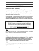
Step 7
Once you are satisfied that the adjustments and settings are correct for minimum
SWR, you can advance the power to 150 Watts if desired. Be sure that MPE
distance standard as defined in Supplement B of the FCC OET Bulletin 65,
version 97-01 is met. Should any arcing be detected, stop transmitting and
check connections and proximity to objects that may be suspect. If arcing seems
to be inside of the MFJ – 933, Loop Tuner, lower output power and re-check for
arcing.
As a courtesy to our fellow hams, for safety and to keep within FCC regulations
you should use the minimum power needed for communications. Power levels of
20 to 50 Watts often provide very reliable communications. The difference
between 50 and 100 Watts is less than ½ S-Unit and is not noticeable on the
receiving end.
Step 8
You can now enjoy operating in your favorite mode. However, if you change
frequency more than about 5 KHz, you may find you’ll need to re-adjust the
TUNING controls for minimum SWR. Rotate TUNING clockwise for higher
frequencies and counter clockwise for lower frequencies. Even greater
frequency excursions can cause the MATCHING control to also require
adjustment.
This concludes the MFJ – 933 Loop Tuner System Operation instructions.
MFJ-933 Loop Tuner
TM
System Accessories
Two Kits are available for use with the MFJ-933 Loop Tuner
TM
, and each
enables the operator expanded operational capabilities, and use of pre-
made/fabricated wires and equipment. These kits are:
• MFJ-57B, which contains a PVC Cross device for mounting a precut and
lugged wire loop to the top cover of the tuner. This flexible 10-gauge wire
loop covers 20 and 30 meters, and the ends have low-resistance lugs.
• MFJ-58B, which contains all of the MFJ-57 items, plus a 40-meter, 15 - 20
meter and 10 - 17meter wire loops, with clips to hang loops as needed.