DISCLAIMER Information in this manual is designed for user purposes only and is not intended to supersede information contained in customer regulations, technical manuals/documents, positional handbooks, or other official publications. The copy of this manual provided to the customer will not be updated to reflect current data.
MFJ-933 Loop TunerTM Instruction & Technical Manual TABLE OF CONTENTS PAGE TOPIC TABLE OF CONTENTS ii LIST OF FIGURES ii LIST OF TABLES ii RF HAZARD PRECAUTIONS 1 INTRODUCTION & SYSTEM FEATURES 7 SYSTEM DESCRIPTION 10 LOOP THEORY 12 SYSTEM SETUP 14 LOOP CONSTRUCTION 15 SYSTEM OPERATION 17 FAST START INSTRUCTIONS 20 TECHNICAL ASSISTANCE 23 LIST OF FIGURES Figure 1 The Electromagnetic Spectrum 2 Figure 2 MFJ-933 Loop Tuner TM 8 Figure 3 MFJ-933 Loop Tuner TM w/ MFJ-57B PVC Cr
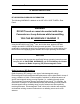
MFJ-933 Loop TunerTM Instruction & Technical Manual RF HAZARD PRECAUTIONS RF HAZARD BACKGROUND INFORMATION The following WARNING is labeled on the MFJ-933 LOOP TUNERTM Rear Panel: WARNING DO NOT touch or come into contact with Loop Connectors or Loop Antenna while transmitting YOU CAN BE SERIOUSLY INJURED !!! Using the MFJ-933 Loop Tuner TM can, and in fact does, produce LETHAL voltages and HIGH CURRENTS during normal operation.
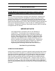
MFJ-933 Loop TunerTM Instruction & Technical Manual RF HAZARD PRECAUTIONS An electromagnetic wave is characterized by its wavelength and frequency. The wavelength is the distance covered by one complete wave cycle. The frequency is the number of waves passing a point in a second. For example, a typical radio wave transmitted by a 2-meter VHF station has a wavelength of about 2 meters and a frequency of about 145 million cycles per second (145 million Hertz): one cycle/second = one Hertz, abbreviated Hz.
MFJ-933 Loop TunerTM Instruction & Technical Manual RF HAZARD PRECAUTIONS FCC OET Bulletin 65, Supplement B, Evaluating Compliance with FCC Guidelines for Human Exposure to Radio frequency Electromagnetic Fields. The FCC Office of Engineering Technology (OET) Bulletin 65, Supplement B, Evaluating Compliance with FCC Guidelines for Human Exposure to Radio frequency Electromagnetic Fields impacts directly the use and operation of the MFJ-933 Loop Tuner TM.
MFJ-933 Loop TunerTM Instruction & Technical Manual RF HAZARD PRECAUTIONS RF RADIATION EXPOSURE CONCERNS Controlled population exposure limits apply to amateur licensees and members of their immediate household (but not their neighbors - see next paragraph). In general, a controlled environment is one for which access is controlled or restricted.
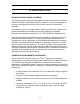
MFJ-933 Loop TunerTM Instruction & Technical Manual RF HAZARD PRECAUTIONS Table 1 Freq (MHz) Indoor & Outdoor Operating Environments at 100 Watts Controlled Population Exposure Uncontrolled Population Exposure (Distance in feet/meters) (Distance in feet/meters) Output Power (Watts) 7.01 1.2 0.36 2.0 0.51 100 7.02 1.2 0.38 2.1 0.75 100 10.01 1.9 0.57 3. 0 0.75 100 10.02 2.3 0.69 3.6 0.92 100 14.01 2.4 0.72 3.8 0.96 100 14.02 2.5 0.77 4.6 0.96 100 18.01 2.8 0.
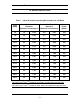
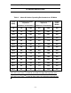
MFJ-933 Loop TunerTM Instruction & Technical Manual RF HAZARD PRECAUTIONS Table 2 Freq (MHz) Indoor & Outdoor Operating Environments at 150 Watts Controlled Population Exposure Uncontrolled Population Exposure (Distance in feet/meters) (Distance in feet/meters) Output Power (Watts) 7.01 1.4 0.44 2.0 0.62 150 7.02 1.5 0.46 2.1 0.91 150 10.01 2.3 0.69 3. 0 0.91 150 10.02 2.7 0.84 3.6 1.11 150 14.01 2.8 0.87 3.8 1.16 150 14.02 3.0 0.93 4.6 1.40 150 18.01 3.4 1.
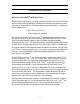
MFJ-933 Loop TunerTM Instruction & Technical Manual INTRODUCTION & FEATURES MFJ-933 LOOP TUNERTM INTRODUCTION The MFJ-933 Loop Tuner TM is a small, versatile, high-efficiency device that turns any wire loop into a high-efficiency multi-band transmitting loop antenna system designed for 50-ohm use at 150 Watts maximum input (all modes).
MFJ-933 Loop TunerTM Instruction & Technical Manual INTRODUCTION & FEATURES Figure 2 MFJ-933 Loop Tuner TM MFJ-933 LOOP TUNERTM FEATURES: • Powerless: No power supply required. • Maximum Input Power: 150 Watts (all modes) • Easy-Carry Handle: Permits easy handling to/from portable location(s) • Small Physical Profile: 6 ¼” W, 9 ½” D, 5 ¼” H • Low Radiation Angle: Rivals full size dipoles. • Quiet Reception: Extremely quiet receiving antenna.
MFJ-933 Loop TunerTM Instruction & Technical Manual INTRODUCTION & FEATURES Figure 3 MFJ-933 Loop Tuner TM with MFJ-57B PVC Cross Loop Antenna Kit Installed -9-
MFJ-933 Loop TunerTM Instruction & Technical Manual SYSTEM DESCRIPTION MFJ-933 LOOP TUNERTM CONTROLS & INDICATORS The MFJ-933 Loop Tuner TM Front Panel controls and indicators function to permit resonating the wire loop at the output, and matching the coaxial line impedance at the input of the tuner. Refer to Figure 4 and the numbered component locations.
MFJ-933 Loop TunerTM Instruction & Technical Manual SYSTEM DESCRIPTION The MFJ-933 Loop Tuner TM Rear Panel connections function to permit connecting the wire loop at the output, and connecting the coaxial line at the input of the tuner. Refer to Figure 5 and the labeled component locations. 1 2 Figure 5 MFJ-933 Loop Tuner TM Rear Panel Connections The loop antenna connects to the Loop Connectors (1) with the two wing nuts provided on the Loop Connector standoff rods.
MFJ-933 Loop TunerTM Instruction & Technical Manual LOOP THEORY LOOP ANTENNA BACKROUND INFORMATION A small loop antenna is one that is characterized by low-noise reception, works well even when mounted at ground level, and has a conductor length or circumference of less than 1/3 wavelength. The ideal small transmitting antenna would have performance equal to a large antenna, and a small loop antenna approaches that performance.
MFJ-933 Loop TunerTM Instruction & Technical Manual LOOP THEORY For minimum ground loss when operating near ground, the loop should be mounted vertically. For higher elevations (relative to the wavelength), horizontal mounting will also give low ground losses. Using freeware-modeling programs, it is possible to improve the efficiency of the loop antenna system by varying the parameters until you optimize your particular operational configuration, even while portable.
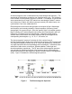
MFJ-933 Loop TunerTM Instruction & Technical Manual SYSTEM SETUP SYSTEM SETUP CONFIGURATION The MFJ-933 Loop Tuner TM setup configuration is simple and consists of the following components: • RF Generator (Transmitter/Transceiver; ~5 Watts minimum) • SWR/Wattmeter • MFJ-933 Loop Tuner TM • Coaxial cable(s) • #10 gauge (or larger) stranded wire cut to approximately 75% of a ¼ wavelength at the chosen resonant frequency Figure 6 is a block diagram of the typical MFJ-933 Loop Tuner TM setup config
MFJ-933 Loop TunerTM Instruction & Technical Manual LOOP CONSTRUCTION LOOP CONSTRUCTION Loop construction for the MFJ – 933 Loop Tuner is reasonably simple, and Table 3 lists the maximum tunable length for the most efficient operation for the upper frequency limit of each band. Each length can be tuned lower in frequency.
MFJ-933 Loop TunerTM Instruction & Technical Manual The applications and parameters can be adjusted easily with the help of the Freeware programs previously mentioned, and you may choose to design a totally new and unique loop antenna for on-air experimentation. Designing an outdoor loop for a band such as 7 MHz could be a challenge and result in a very good radiator and especially good receiving antenna for DX-ing and/or ragchewing.
MFJ-933 Loop TunerTM Instruction & Technical Manual SYSTEM OPERATION MFJ-933 LOOP TUNERTM OPERATION The most important aspect of using the MFJ-933 Loop Tuner TM is it opens-up opportunity for Hams to once again experiment while enjoying operating at the same time. Imagine how exciting it can be to establish contact with a distant station using an antenna that you designed for the first time.
MFJ-933 Loop TunerTM Instruction & Technical Manual SYSTEM OPERATION Step 4 Make the following preliminary settings on the controls of the Loop Tuner: • • TUNING control to position “0, Low Freq”. MATCHING control to position “10, Min C”. Step 5 Tune the transceiver or receiver to the band and frequency of interest and “Earball” tune the MFJ-933 Loop Tuner controls for maximum noise and S-Meter reading.
MFJ-933 Loop TunerTM Instruction & Technical Manual Step 7 Once you are satisfied that the adjustments and settings are correct for minimum SWR, you can advance the power to 150 Watts if desired. Be sure that MPE distance standard as defined in Supplement B of the FCC OET Bulletin 65, version 97-01 is met. Should any arcing be detected, stop transmitting and check connections and proximity to objects that may be suspect.
MFJ-933 Loop TunerTM Instruction & Technical Manual FAST-START INSTRUCTIONS FAST START OPTION Although careful and complete reading of the technical manual is certainly foremost when receiving new equipment, MFJ-933 Loop Tuner TM operation can be achieved with minimum time and effort as long as certain and specific instructions are followed.
MFJ-933 Loop TunerTM Instruction & Technical Manual FAST-START INSTRUCTIONS Step 3 Pre-set the MFJ – 933 Loop Tuner controls to the following settings for the 14.2 MHz operation (settings are approximate, but should be reasonable): • • TUNING control to position “4 ½ ”. MATCHING control to position “9”. Step 4 Tune the transceiver or receiver to the 20 meter band and frequency of interest and “Ear-ball” fine-tune the MFJ-933 Loop Tuner TM controls for maximum noise and S-Meter reading.
MFJ-933 Loop TunerTM Instruction & Technical Manual FAST-START INSTRUCTIONS Step 7 You can now enjoy operating in your favorite mode. However, if you change frequency more than about 5 KHz, you may find you’ll need to re-adjust the TUNING controls for minimum SWR. Rotate TUNING clockwise for higher frequencies and counter clockwise for lower frequencies. Even greater frequency excursions can cause the MATCHING control to also require adjustment.
MFJ-933 Loop TunerTM Instruction & Technical Manual TECHNICAL ASSISTANCE TECHNICAL ASSISTANCE If you have any problem with this unit first check the appropriate section of this manual. If the manual does not reference your problem or reading the manual does not solve your problem, you may call MFJ Technical Service at 662-3230549 or the MFJ Factory at 662-323-5869.